Cooling equipment for producing compound fertilizer

A technology of cooling equipment and compound fertilizer, which is applied in the field of compound fertilizer, can solve the problems of increasing the production cost of enterprises, polluting the atmosphere, and wasting energy of air supply equipment, etc., and achieve the effect of improving cooling efficiency, reducing power loss, and reducing production cost

Pending Publication Date: 2022-08-05
GARSONI FERTILIZER PINGYUAN
View PDF0 Cites 0 Cited by
  • Summary
  • Abstract
  • Description
  • Claims
  • Application Information

AI Technical Summary

Problems solved by technology

[0002] The production of compound fertilizer includes batching, mixing, steam granulation, drying, cooling, filtering and packaging. The cooling step is to quickly cool down the dried and high-temperature compound fertilizer particles to improve production efficiency and quickly enter the filter packaging. The first step is to use an organic fertilizer cooler to cool the fertilizer granules. Specifically, the fertilizer granules are loaded into the drum of the cooler, and then cold air (usually air) is blown in. During the flow, the cold air drives the fertilizer granules. The heat dissipated, but the flow path of the cold air is linear and can only be blown to the surface of the fertilizer granules, without sufficient heat exchange with the fertilizer granules, it will flow out, the efficiency is low, and it will cause the energy waste of the air supply equipment, no doubt Increase the production cost of the enterprise, and the fertilizer particles will raise dust during the movement. The dust will flow out with the cold wind, and the direct discharge will pollute the atmosphere. The installation of dust removal equipment will increase the cost of use

Method used


Image

  • Cooling equipment for producing compound fertilizer
  • Cooling equipment for producing compound fertilizer
  • Cooling equipment for producing compound fertilizer

Examples


Embodiment Construction

[0020] The present invention will be described in further detail below with reference to the accompanying drawings and specific embodiments. The embodiments of the present invention are presented for purposes of illustration and description, and are not intended to be exhaustive or to limit the invention to the forms disclosed. Many modifications and variations will be apparent to those of ordinary skill in the art. The embodiment was chosen and described in order to better explain the principles of the invention and the practical application, and to enable others of ordinary skill in the art to understand the invention for various embodiments with various modifications as are suited to the particular use.

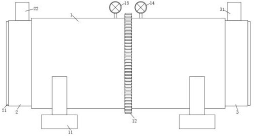
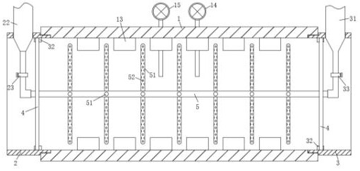
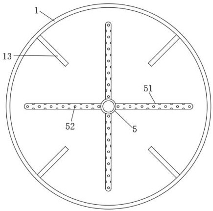
[0021] A cooling device for producing compound fertilizer, such as Figure 1-5 As shown, it includes a main cylinder 1, a first side cylinder 2, a second side cylinder 3, a sealing plate 4 and a main air pipe 5. The first side cylinder 2 and the second side cylinder 3 are...


PUM


Abstract

The cooling equipment comprises a main cylinder, a first side cylinder, a second side cylinder, a sealing plate and a main air pipe, the first side cylinder and the second side cylinder are located on the two sides of the main cylinder, and the main cylinder is rotatably installed between the first side cylinder and the second side cylinder; the two sealing plates are detachably installed in the first side cylinder and the second side cylinder respectively to seal the main cylinder, the main air pipe is horizontally located at the central axis position in the main cylinder, and the two ends of the main air pipe penetrate out of the sealing plates on the two sides respectively. A plurality of branch air pipes for contacting compound fertilizer are arranged on the side surface of the main air pipe, and a plurality of lifting plates for lifting the compound fertilizer are arranged on the inner wall of the main cylinder. According to the invention, air intermittently enters the main cylinder, passes through the air-distributing pipe, is in full contact with compound fertilizer moving from top to bottom and performs heat exchange, and is filtered by the air-distributing pipe when intermittently flowing out, so that the cooling efficiency is improved, the power loss of cold air flowing is reduced, the production cost is reduced, and the flowing-out air is dust-free and meets the environment-friendly emission requirement.

Description

technical field [0001] The invention relates to the field of compound fertilizers, and more particularly, to a cooling device for producing compound fertilizers. Background technique [0002] The production of compound fertilizer includes batching, mixing, steam granulation, drying, cooling, filtration and packaging. It is a common method to use an organic fertilizer cooler to cool the fertilizer particles. Specifically, the fertilizer particles are loaded into the drum of the cooler, and then cold air (usually air) is blown in. The cold air drives the fertilizer particles in the process of flowing. The heat dissipated, but the flow path of the cold air is linear, and it can only be blown to the surface of the fertilizer particles. Without sufficient heat exchange with the fertilizer particles, it will flow out. The efficiency is low, and it will cause energy waste of the air supply equipment. Undoubtedly It increases the production cost of the enterprise, and the fertilize...

Claims


Application Information

Patent Timeline
Patent Type & Authority Applications(China)
IPC IPC(8): F28C3/18F28F13/12F28F19/01F25D31/00
CPCF28C3/18F28F13/125F28F19/01F25D31/00
Inventor 杨锦罗云华
Owner GARSONI FERTILIZER PINGYUAN
Why Eureka
Try Eureka