Target identification method based on millimeter wave radar and terminal equipment
A millimeter wave radar and terminal equipment technology, applied in the field of information processing, can solve problems such as reducing the efficiency of identification
Pending Publication Date: 2022-08-05
HISENSE GRP HLDG CO LTD
0 Cites 0 Cited by
AI-Extracted Technical Summary
Problems solved by technology
[0004] In the prior art, the target recognition of millimeter-wave radar is based on micro-Doppler feature extraction. This method requi...
Abstract
The invention provides a target identification method based on millimeter wave radar and terminal equipment. Comprising the following steps: for any frame of frame data acquired by a millimeter wave radar, determining position coordinates of each target point according to a distance between each target point and the millimeter wave radar determined by the frame data, and an azimuth angle and a pitch angle formed by each target point and the millimeter wave radar; clustering the target points by using the determined position coordinates of the target points to obtain at least one target area; for any target area, performing rasterization processing on the target area by using the position coordinates of each target point in the target area and the speed of each target point determined by the frame data to obtain a raster image; inputting the raster image into a preset target recognition model, and determining a target category and a target action corresponding to the target area; therefore, according to the method and the device, the target is identified only by one frame of data, and accumulation of multiple frames is not needed, so that the time delay of target identification is reduced, and the target identification efficiency is improved.
Application Domain
Character and pattern recognitionRadio wave reradiation/reflection +1
Technology Topic
PhysicsAzimuth +6
Image
Examples
- Experimental program(1)
Example Embodiment
[0074] In order to make the purposes, technical solutions and advantages of the embodiments of the present disclosure clearer, the technical solutions in the embodiments of the present disclosure will be described clearly and completely below with reference to the accompanying drawings in the embodiments of the present disclosure. Obviously, the described embodiments These are some, but not all, embodiments of the present disclosure. Based on the embodiments in the present disclosure, all other embodiments obtained by those of ordinary skill in the art without creative efforts shall fall within the protection scope of the present disclosure.
[0075] In the embodiments of the present disclosure, the term "and/or" describes the association relationship of associated objects, and indicates that there can be three kinds of relationships. For example, A and/or B can indicate that A exists alone, A and B exist at the same time, and B exists alone these three situations. The character "/" generally indicates that the associated objects are an "or" relationship.
[0076] The application scenarios described in the embodiments of the present disclosure are for the purpose of illustrating the technical solutions of the embodiments of the present disclosure more clearly, and do not constitute a limitation on the technical solutions provided by the embodiments of the present disclosure. Those of ordinary skill in the art know that with the development of new application scenarios It appears that the technical solutions provided by the embodiments of the present disclosure are also applicable to similar technical problems. Wherein, in the description of the present disclosure, unless otherwise specified, "plurality" means two or more.
[0077] In the prior art, target recognition by millimeter-wave radar is based on micro-Doppler feature extraction. This method requires the accumulation of multiple frames, resulting in a certain delay in target recognition, which reduces the efficiency of recognition.
[0078] Therefore, the present disclosure provides a target recognition method for a millimeter-wave radar. The position coordinates of each target point are determined from a frame of data, and the position coordinates of each target point are used for clustering to obtain a plurality of target areas. The gridded target area is input into the target recognition model to determine the target category and action. Therefore, the present disclosure only needs one frame of data to recognize the target, and does not need to accumulate multiple frames, thus reducing the delay of target recognition and improving the efficiency of target recognition.
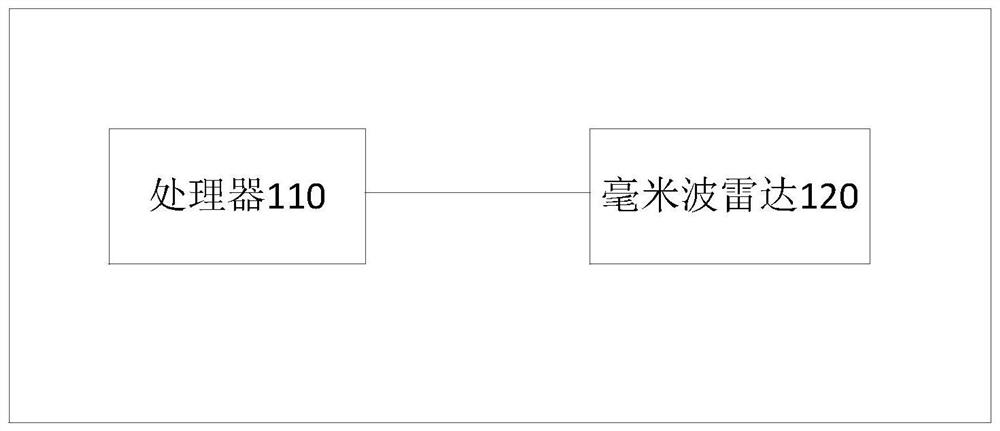
[0079] Before introducing the solution of the present disclosure in detail, the structure of the terminal device according to the embodiment of the present disclosure is first introduced. figure 1 This is a schematic structural diagram of a terminal device in the present disclosure. like figure 1 As shown, the terminal device in the embodiment of the present disclosure includes: a processor 110 and a millimeter-wave radar 120 . Wherein, the millimeter-wave radar is used to collect frame data; the processor 110 is used for any frame of frame data collected by the millimeter-wave radar 120, according to each target point determined by the frame data and the millimeter-wave The distance of the radar, the azimuth angle and the elevation angle formed by each target point and the millimeter wave radar, determine the position coordinates of each target point; the processor 110 uses the determined position coordinates of each target point to cluster each target point. class to obtain at least one target area; for any target area, use the position coordinates of each target point in the target area and the speed of each target point determined by the frame data to rasterize the target area , obtain a grid image; and input the grid image into a preset target recognition model to determine the target category and target action corresponding to the target area.
[0080] In one embodiment, the processor 110 rasterizes the target area by using the position coordinates of each target point in the target area and the speed of each target point determined by the frame data. When processing, when getting a raster image, it is specifically configured as:
[0081] dividing the target area into grid blocks of a specified size;
[0082] Determine the relative position coordinates of each target point by using the position coordinates of the target point with the smallest distance from the millimeter wave radar in the target area, and the position coordinates of each target point;
[0083] Determine the grid block where each target point is located according to the relative position coordinates of each target point and the position of each grid block in the target area;
[0084] Using the preset correspondence between the speed of each target point and the grayscale value, determine the grayscale value corresponding to the speed of each target point;
[0085] The gray value of the grid block is set according to the gray value of the target point contained in the grid block, and the gray value of each grid block not including the target point is set to the specified gray value, wherein the specified gray value The degree value is not the same as the gray value of the raster block containing the target point.
[0086] In one embodiment, when the processor 110 executes the setting of the grayscale value of the grid block according to the grayscale value of the target point contained in the grid block, it is specifically configured to:
[0087] If the number of target points included in the grid block is one target point, the gray value of the grid block is set to the gray value corresponding to the target point; and,
[0088] If the number of target points included in the grid block is a plurality of target points, the grayscale value of the grid block is set as the average value of the grayscale values corresponding to each target point.
[0089] In one embodiment, after performing the clustering of each target point using the determined position coordinates of each target point to obtain at least one target area, the processor 110 is further configured to:
[0090] Determine the position coordinates of the target area according to the position coordinates of each target point in each target area; and,
[0091] The speed of each target area is determined by the speed of each target point in each target area.
[0092] In one embodiment, the processor 110 is performing the process according to the distance between each target point and the millimeter-wave radar, the azimuth angle and the elevation angle formed by each target point and the millimeter-wave radar determined from the frame data. , when determining the position coordinates of each target point, it is specifically configured as:
[0093] Determine the abscissa and ordinate of each target point by using the determined distance between each target point and the millimeter-wave radar, the azimuth angle and the elevation angle formed by each target point and the millimeter-wave radar; and,
[0094] The vertical coordinates of each target point are determined according to the distance between each target point and the millimeter wave radar and the pitch angle.
[0095] In one embodiment, the processor 110 is further configured to:
[0096] The object recognition model is trained according to:
[0097] Input the target recognition training sample into the target recognition model, perform feature extraction on the grid image to obtain target feature information, and match the target feature information with the saved target category features to determine the target with the highest matching degree Category features; the training samples include grid images and labeling target categories, and the labeling target categories include target categories and target actions;
[0098] Compare the target category feature with the highest matching degree with the labeled target category to obtain an error value;
[0099] When the error value does not meet the specified condition, after adjusting the training parameters of the target recognition model, return to the step of inputting target recognition training samples into the target recognition model until the error value meets the specified condition, then End the training of the target recognition model.
[0100] After the terminal device of the embodiment of the present disclosure is introduced, the technical solution of the present disclosure will be introduced in detail.
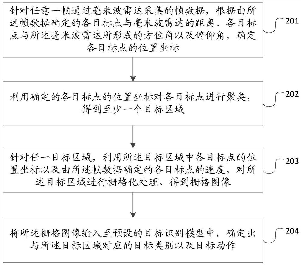
[0101] figure 2 It is a schematic flowchart of the target recognition method based on millimeter wave radar of the present disclosure, which may include the following steps:
[0102]Step 201: For any frame of frame data collected by the millimeter-wave radar, according to the distance between each target point and the millimeter-wave radar determined by the frame data, and the azimuth and pitch formed by each target point and the millimeter-wave radar. Angle, determine the position coordinates of each target point;
[0103] It should be noted that: the target point in the embodiment of the present disclosure is the reflection point on the target object that reflects the electromagnetic wave back after the millimeter-wave radar transmits the electromagnetic wave to the target object. And the frame data in the embodiment of the present disclosure is the intermediate frequency signal of the millimeter wave radar sampled by the ADC.
[0104] in:
[0105] a. The method for determining the distance between each target point and the millimeter-wave radar is: perform Fourier transform on the number of chirp signals in the frame data, determine the frequency, and then determine the relationship between each target point and the millimeter wave radar by formula (1). Distance of mmWave radar:
[0106]
[0107] Among them, d is the distance between the target point and the millimeter-wave radar, f is the frequency, c is the speed of light, and s is the slope of the chirp signal.
[0108] b. The method for determining the speed of each target point is: performing Fourier transform on the sampling number of each chirp signal to obtain the phase. Then the speed of each target point is determined by formula (2):
[0109]
[0110] Among them, λ is the wavelength corresponding to the starting frequency of the millimeter-wave radar, ω is the phase, and T C is the time interval between two chirps.
[0111] c. The method of determining the azimuth angle formed by each target point and the millimeter-wave radar is as follows: respectively perform Fourier transform on the number of antennas in the horizontal direction and the number of antennas in the vertical direction of each chirp signal to obtain the horizontal phase and Vertical phase; then determine the azimuth angle formed by each target point and the millimeter-wave radar by formula (3), and determine the pitch angle formed by each target point and the millimeter-wave radar by formula (4):
[0112]
[0113] Among them, θ is the azimuth angle formed by the target point and the millimeter-wave radar, ω 1 is the horizontal phase, and d is the number of antennas of the millimeter-wave radar.
[0114]
[0115] in, is the pitch angle formed by the target point and the millimeter-wave radar, ω 2 is the vertical phase.
[0116] In one embodiment, the aforementioned step 202 may be implemented as: using the determined distances between the target points and the millimeter-wave radar, azimuth angles and elevations formed by the target points and the millimeter-wave radar The abscissa and ordinate of each target point are determined respectively according to the angle; the vertical coordinate of each target point is determined according to the distance between each target point and the millimeter wave radar and the pitch angle.
[0117] Wherein, the abscissa, ordinate and vertical coordinate of the point of each target can be determined by formula (5):
[0118]
[0119] where p x is the abscissa of the target point, p y is the ordinate of the target point, p z is the vertical coordinate of the target point, where r is the distance between the target point and the millimeter-wave radar, θ is the azimuth angle formed by the target point and the millimeter-wave radar, is the pitch angle formed by the target point and the millimeter wave radar.
[0120] Step 202: Cluster each target point by using the determined position coordinates of each target point to obtain at least one target area;
[0121] The clustering algorithm used in the embodiment of the present disclosure is a density clustering algorithm.
[0122] Take the DBSCAN algorithm as an example to explain the clustering process: for any target point, take the target point as the center of the circle, and use the preset radius to draw a circle. If the total number of target points in the circle is less than the specified threshold, then determine the The point is the boundary point. If the total number of target points in the circle is not less than the specified threshold, the point is determined as the core point. For any core point, each density-reachable point of the core point is determined, and the area formed by the density-reachable points of the core point is the target area. In this way, each target area is determined.
[0123] It should be noted that the density clustering algorithm in the embodiments of the present disclosure includes, but is not limited to, the DBSCAN algorithm, and the above-mentioned embodiments of the present disclosure are only for explanation and do not limit the present disclosure.
[0124] Step 203: For any target area, use the position coordinates of each target point in the target area and the speed of each target point determined by the frame data to perform grid processing on the target area to obtain a grid image ;
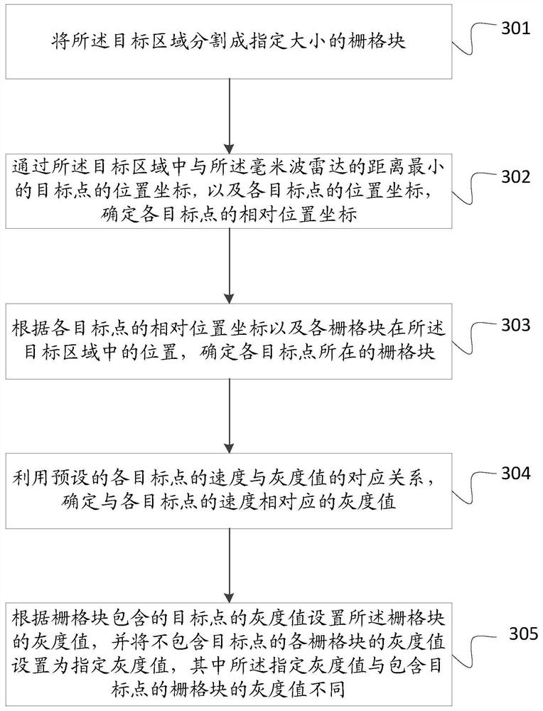
[0125] In one embodiment, step 203 may be implemented as: image 3 shown, may include the following steps:
[0126] Step 301: Divide the target area into grid blocks of a specified size;
[0127] Step 302: Determine the relative position coordinates of each target point through the position coordinates of the target point with the smallest distance from the millimeter-wave radar in the target area, and the position coordinates of each target point;
[0128] Step 303: Determine the grid block where each target point is located according to the relative position coordinates of each target point and the position of each grid block in the target area;
[0129] Step 304: Using the preset correspondence between the speed of each target point and the gray value, determine the gray value corresponding to the speed of each target point;
[0130] Step 305: Set the gray value of the grid block according to the gray value of the target point included in the grid block, and set the gray value of each grid block not including the target point to the specified gray value, wherein all The specified gray value is different from the gray value of the grid block containing the target point.
[0131] For example, as Figure 4 As shown, there are two target areas, namely target area 1 and target area 2. Figure 4 The raster blocks in are the raster images after rasterizing the target area 1 and the target area 2 respectively. Among them, the gray value of the grid block corresponds to the speed of the target point contained in the grid block. Among them, the corresponding relationship between the gray value and the speed of the target point can be shown in Table 1:
[0132] Table 1:
[0133] target point speed grayscale value A~B (excluding B) m B~C n C~D p … …
[0134] In one embodiment, step 305 may be implemented as: if the number of target points included in the grid block is one target point, set the gray value of the grid block to the gray value corresponding to the target point and, if the number of target points contained in the grid block is a plurality of target points, setting the grayscale value of the grid block as the average value of the grayscale values corresponding to each target point.
[0135] For example, if the grid block 1 only contains the target point 1, if the gray value corresponding to the target point 1 is a, the gray value of the grid block 1 is set to a. If the target points included in grid block 2 include target point 2 and target point 3, if the grayscale value corresponding to target point 2 is b, the grayscale value corresponding to target point 3 is c. Then set the gray value of grid block 2 to
[0136] Among them, it should be noted that the size of the grid block can be set according to the actual situation. The size of the grid blocks is not limited in this disclosure.
[0137] Among them, the larger the size of the grid block is, the smaller the amount of calculation is, but the quality of the obtained grid image is lower. The smaller the size of the grid block is, the greater the amount of computation, but the higher the quality of the resulting grid image.
[0138] Step 204: Input the grid image into a preset target recognition model, and determine the target category and target action corresponding to the target area.
[0139] For example, the output results can be people walking, dogs running, and so on.
[0140] In one embodiment, the object recognition model is trained according to:
[0141] Input the target recognition training sample into the target recognition model, perform feature extraction on the grid image to obtain target feature information, and match the target feature information with the saved target category features to determine the target with the highest matching degree Category features; the training samples include grid images and labeled target categories, and the labeled target categories include target categories and target actions; compare the target category features with the highest matching degree with the labeled target categories to obtain an error value ; When the error value does not meet the specified condition, then after adjusting the training parameters of the target recognition model, return to perform the step of inputting the target recognition training sample into the target recognition model, until the error value meets the specified condition, Then, the training of the target recognition model is ended.
[0142] In order to make the information on target recognition more comprehensive, in one embodiment, the position coordinates of the target area are determined according to the position coordinates of each target point in each target area; and, the speed of each target point in each target area is determined by determining out of the target area.
[0143] Wherein, the average value of the position coordinates of each target point in each target area may be used as the position coordinate of the target area. And the average value of the speed of each target point in each target area can be used as the speed of the target area.
[0144] For example, if the target points in the target area include target point 1, target point 2, target point 3 and target point 4. If the position coordinates of target point 1 are (10, 15.20), the position coordinates of target point 2 are (15, 13, 18), the position coordinates of target point 3 are (17, 17, 19) and the position coordinates of target point 4 is (14, 15, 11), then the position coordinates of the target area can be determined as (14, 15, 17). If the speed of target point 1 is 1m/s, the speed of target point 2 is 1.5m/s, the speed of target point 3 is 1m/s, and the speed of target point 4 is 1.5m/s, then the speed of the target area is determined. is 1.25m/s.
[0145] Thus, when the method is applied to a car, the user can control the speed and the like of the vehicle according to the speed and position of the object.
[0146] In order to further understand the technical solutions of the present disclosure, the following combination Figure 5 A detailed description may include the following steps:
[0147] Step 501: For any frame of frame data collected by the millimeter-wave radar, according to the distance between each target point and the millimeter-wave radar determined by the frame data, the azimuth angle and the pitch formed by each target point and the millimeter-wave radar Angle, determine the position coordinates of each target point;
[0148] Step 502: Use the determined position coordinates of each target point to cluster each target point to obtain at least one target area;
[0149]Step 503: Determine the position coordinates of the target area according to the position coordinates of each target point in each target area; and determine the speed of the target area by the speed of each target point in each target area;
[0150] Wherein, the execution sequence between step 503 and step 504 is not limited in the present disclosure. Step 503 may be executed first, and then step 504 may be executed; or step 504 may be executed first, and then step 503 may be executed; or step 503 and step 503 may be executed 504 is executed concurrently.
[0151] Step 504: Divide the target area into grid blocks of a specified size;
[0152] Step 505: Determine the relative position coordinates of each target point through the position coordinates of the target point with the smallest distance from the millimeter wave radar in the target area, and the position coordinates of each target point;
[0153] Step 506: Determine the grid block where each target point is located according to the relative position coordinates of each target point and the position of each grid block in the target area;
[0154] Step 507: Using the preset correspondence between the speed of each target point and the gray value, determine the gray value corresponding to the speed of each target point;
[0155] Step 508: Set the gray value of the grid block according to the gray value of the target point included in the grid block, and set the gray value of each grid block not including the target point to the specified gray value, where all The specified gray value is different from the gray value of the grid block containing the target point;
[0156] Step 509: For any target area, use the position coordinates of each target point in the target area and the speed of each target point determined by the frame data to perform grid processing on the target area to obtain a grid image ;
[0157] Step 510: Input the grid image into a preset target recognition model, and determine the target category and target action corresponding to the target area.
[0158] Based on the same disclosed concept, the millimeter-wave radar-based target identification method of the present disclosure can also be implemented by a millimeter-wave radar-based target identification device. The effect of the target recognition based on the millimeter-wave radar is similar to the effect of the foregoing method, and will not be repeated here.
[0159] Image 6 It is a schematic structural diagram of a target identification device based on a millimeter wave radar according to an embodiment of the present disclosure.
[0160] like Image 6 As shown, the millimeter-wave radar-based target identification device 600 of the present disclosure may include a target point position coordinate determination module 610 , a target area determination module 620 , a rasterization processing module 630 and a target identification module 640 .
[0161] The target point position coordinate determination module 610 is used for the frame data collected by the millimeter wave radar for any frame, according to the distance between each target point and the millimeter wave radar determined by the frame data, and the distance between each target point and the millimeter wave radar determined by the frame data. The formed azimuth angle and pitch angle determine the position coordinates of each target point;
[0162] a target area determination module 620, configured to perform clustering on each target point by using the determined position coordinates of each target point to obtain at least one target area;
[0163] The rasterization processing module 630 is configured to, for any target area, use the position coordinates of each target point in the target area and the speed of each target point determined by the frame data to rasterize the target area Process to get a raster image;
[0164] The target recognition module 640 is configured to input the grid image into a preset target recognition model, and determine the target category and target action corresponding to the target area.
[0165] In one embodiment, the rasterization processing module 630 is specifically configured to:
[0166] a dividing unit 631, configured to divide the target area into grid blocks of a specified size;
[0167] A relative position coordinate determination unit 632, configured to determine the relative position coordinates of each target point by the position coordinates of the target point with the smallest distance from the millimeter wave radar in the target area, and the position coordinates of each target point;
[0168] The grid block determination unit 633 where the target point is located is used to determine the grid block where each target point is located according to the relative position coordinates of each target point and the position of each grid block in the target area;
[0169] The target point gray value determination unit 634 is used to determine the gray value corresponding to the speed of each target point by using the preset correspondence between the speed of each target point and the gray value;
[0170] The grid block gray value setting unit 635 is configured to set the gray value of the grid block according to the gray value of the target point included in the grid block, and set the gray value of each grid block not including the target point Set to the specified gray value, where the specified gray value is different from the gray value of the grid block containing the target point.
[0171] In one embodiment, the grid block gray value setting unit 635 is specifically configured to:
[0172] If the number of target points included in the grid block is one target point, the gray value of the grid block is set to the gray value corresponding to the target point; and,
[0173] If the number of target points included in the grid block is a plurality of target points, the grayscale value of the grid block is set as the average value of the grayscale values corresponding to each target point.
[0174] In one embodiment, the apparatus further comprises:
[0175] A target position determination module 650, configured to determine the position coordinates of the target area according to the position coordinates of each target point in each target area;
[0176] The target speed determination module 660 is configured to determine the speed of the target area according to the speed of each target point in each target area.
[0177] In one embodiment, the target point position coordinate determination module 610 is specifically used for:
[0178] Determine the abscissa and ordinate of each target point by using the determined distance between each target point and the millimeter-wave radar, the azimuth angle and the elevation angle formed by each target point and the millimeter-wave radar; and,
[0179] The vertical coordinates of each target point are determined according to the distance between each target point and the millimeter wave radar and the pitch angle.
[0180] In one embodiment, the apparatus further comprises:
[0181] The target recognition model training module 670 is used to train the target recognition model according to the following methods:
[0182] Input the target recognition training sample into the target recognition model, perform feature extraction on the grid image to obtain target feature information, and match the target feature information with the saved target category features to determine the target with the highest matching degree Category features; the training samples include grid images and labeling target categories, and the labeling target categories include target categories and target actions;
[0183] Compare the target category feature with the highest matching degree with the labeled target category to obtain an error value;
[0184] When the error value does not meet the specified condition, after adjusting the training parameters of the target recognition model, return to the step of inputting target recognition training samples into the target recognition model until the error value meets the specified condition, then End the training of the target recognition model.
[0185] After introducing a millimeter-wave radar-based target identification method and a terminal device according to an exemplary embodiment of the present disclosure, next, an electronic device according to another exemplary embodiment of the present disclosure is introduced.
[0186] As will be appreciated by one skilled in the art, various aspects of the present disclosure may be implemented as a system, method or program product. Therefore, various aspects of the present disclosure can be embodied in the following forms: a complete hardware implementation, a complete software implementation (including firmware, microcode, etc.), or a combination of hardware and software aspects, which may be collectively referred to herein as implementations "circuit", "module" or "system".
[0187] In some possible implementations, an electronic device according to the present disclosure may include at least at least one processor, and at least one computer storage medium. The computer storage medium stores program codes, which, when executed by the processor, cause the processor to execute the steps in the millimeter-wave radar-based target recognition methods described above in this specification according to various exemplary embodiments of the present disclosure. For example, the processor can execute figure 2 shown in steps 201-204.
[0188] Refer below Figure 7 The electronic device 700 according to this embodiment of the present disclosure will be described. Figure 7 The electronic device 700 shown is only an example, and should not impose any limitations on the functions and scope of use of the embodiments of the present disclosure.
[0189] like Figure 7 As shown, electronic device 700 takes the form of a general-purpose electronic device. Components of the electronic device 700 may include, but are not limited to, the above-mentioned at least one processor 701 , the above-mentioned at least one computer storage medium 702 , and a bus 703 connecting different system components (including the computer storage medium 702 and the processor 701 ).
[0190] Bus 703 represents one or more of several types of bus structures, including a computer storage medium bus or computer storage medium controller, a peripheral bus, a processor, or a local bus using any of a variety of bus structures.
[0191] Computer storage media 702 may include readable media in the form of volatile computer storage media, such as random access computer storage media (RAM) 721 and/or cache storage media 722, and may further include read-only computer storage media (ROM) 723.
[0192] The computer storage medium 702 may also include a program/utility 725 having a set (at least one) of program modules 724 including, but not limited to, an operating system, one or more application programs, other program modules, and program data , each or some combination of these examples may include an implementation of a network environment.
[0193] Electronic device 700 may also communicate with one or more external devices 704 (eg, keyboards, pointing devices, etc.), may also communicate with one or more devices that enable a user to interact with electronic device 700, and/or communicate with the electronic device 700 can communicate with any device (eg, router, modem, etc.) that communicates with one or more other electronic devices. Such communication may take place through input/output (I/O) interface 705 . Also, the electronic device 700 may communicate with one or more networks (eg, a local area network (LAN), a wide area network (WAN), and/or a public network such as the Internet) through a network adapter 706 . As shown, network adapter 706 communicates with other modules for electronic device 700 via bus 703 . It should be understood that, although not shown, other hardware and/or software modules may be used in conjunction with electronic device 700, including but not limited to: microcode, device drivers, redundant processors, external disk drive arrays, RAID systems, tape drives and data backup storage systems.
[0194]In some possible implementations, various aspects of the millimeter-wave radar-based target identification method provided by the present disclosure can also be implemented in the form of a program product, which includes program code, and when the program product runs on a computer device , the program code is used to cause the computer device to execute the steps in the millimeter-wave radar-based target identification method described above in this specification according to various exemplary embodiments of the present disclosure.
[0195] The program product may employ any combination of one or more readable media. The readable medium may be a readable signal medium or a readable storage medium. The readable storage medium may be, for example, but not limited to, an electrical, magnetic, optical, electromagnetic, infrared, or semiconductor system, apparatus or device, or a combination of any of the above. More specific examples (non-exhaustive list) of readable storage media include: electrical connections with one or more wires, portable disks, hard disks, random access computer storage media (RAM), read only computer storage media (ROM) ), erasable programmable read-only computer storage media (EPROM or flash memory), optical fiber, portable compact disc read-only computer storage media (CD-ROM), optical computer storage media, magnetic computer storage media, or any of the foregoing suitable combination.
[0196] The program product for millimeter-wave radar-based target recognition of embodiments of the present disclosure may employ a portable compact disk read-only computer storage medium (CD-ROM) and include program code, and may be executed on an electronic device. However, the program product of the present disclosure is not limited thereto, and in this document, a readable storage medium may be any tangible medium that contains or stores a program that can be used by or in conjunction with an instruction execution system, apparatus, or device.
[0197] A readable signal medium may include a propagated data signal in baseband or as part of a carrier wave, carrying readable program code therein. Such propagated data signals may take a variety of forms including, but not limited to, electromagnetic signals, optical signals, or any suitable combination of the foregoing. A readable signal medium can also be any readable medium other than a readable storage medium that can transmit, propagate, or transport the program for use by or in connection with the instruction execution system, apparatus, or device.
[0198] Program code embodied on a readable medium may be transmitted using any suitable medium including, but not limited to, wireless, wireline, optical fiber cable, RF, etc., or any suitable combination of the foregoing.
[0199] Program code for performing the operations of the present disclosure may be written in any combination of one or more programming languages, including object-oriented programming languages—such as Java, C++, etc., as well as conventional procedural programming Language - such as the "C" language or similar programming language. The program code may execute entirely on the user's electronic device, partly on the user's device, as a stand-alone software package, partly on the user's electronic device and partly on a remote electronic device, or entirely on the remote electronic device or server execute on. In the case of remote electronic equipment, the remote electronic equipment may be connected to the user electronic equipment through any kind of network, including a local area network (LAN) or a wide area network (WAN), or may be connected to external electronic equipment (eg, using Internet services provider to connect via the Internet).
[0200] It should be noted that although several modules of the apparatus are mentioned in the above detailed description, this division is merely exemplary and not mandatory. Indeed, in accordance with embodiments of the present disclosure, the features and functions of two or more modules described above may be embodied in one module. Conversely, the features and functions of one module described above may be further divided into multiple modules to be embodied.
[0201] Furthermore, although the operations of the disclosed methods are depicted in the figures in a particular order, it is not required or implied that the operations must be performed in the particular order, or that all illustrated operations must be performed to achieve desirable results. Additionally or alternatively, certain steps may be omitted, multiple steps may be combined to be performed as one step, and/or one step may be decomposed into multiple steps to be performed.
[0202] As will be appreciated by one skilled in the art, embodiments of the present disclosure may be provided as a method, system, or computer program product. Accordingly, the present disclosure may take the form of an entirely hardware embodiment, an entirely software embodiment, or an embodiment combining software and hardware aspects. Furthermore, the present disclosure may take the form of a computer program product embodied on one or more computer-usable storage media (including, but not limited to, disk computer storage media, CD-ROMs, optical computer storage media, etc.) having computer-usable program code embodied therein. form.
[0203] The present disclosure is described with reference to flowchart illustrations and/or block diagrams of methods, apparatus (systems), and computer program products according to the present disclosure. It will be understood that each flow and/or block in the flowchart illustrations and/or block diagrams, and combinations of flows and/or blocks in the flowchart illustrations and/or block diagrams, can be implemented by computer program instructions. These computer program instructions may be provided to the processor of a general purpose computer, special purpose computer, embedded processor or other programmable data processing device to produce a machine such that the instructions executed by the processor of the computer or other programmable data processing device produce in the process of realization Figure 1 process or processes and/or blocks Figure 1 A means for the functions specified in a block or blocks.
[0204] These computer program instructions may also be stored in a computer-readable computer storage medium capable of directing a computer or other programmable data processing apparatus to function in a particular manner, such that the instructions stored in the computer-readable computer storage medium result in the manufacture of means including the instructions product, the command device is implemented in the process Figure 1 process or processes and/or blocks Figure 1 the function specified in a box or boxes.
[0205] These computer program instructions can also be loaded on a computer or other programmable data processing device to cause a series of operational steps to be performed on the computer or other programmable device to produce a computer-implemented process such that Instructions are provided for implementing the process in Figure 1 process or processes and/or blocks Figure 1 The steps of the function specified in the box or boxes.
[0206] It will be apparent to those skilled in the art that various modifications and variations can be made in the present disclosure without departing from the spirit and scope of the present disclosure. Thus, provided that these modifications and variations of the present disclosure fall within the scope of the claims of the present disclosure and their equivalents, the present disclosure is also intended to cover such modifications and variations.
PUM


Description & Claims & Application Information
We can also present the details of the Description, Claims and Application information to help users get a comprehensive understanding of the technical details of the patent, such as background art, summary of invention, brief description of drawings, description of embodiments, and other original content. On the other hand, users can also determine the specific scope of protection of the technology through the list of claims; as well as understand the changes in the life cycle of the technology with the presentation of the patent timeline. Login to view more.