Power switch cabinet for digital rural construction

A technology for power switches and switch cabinets, applied in the field of digital rural construction power switch cabinets, can solve problems such as short circuit of functional units, no warehouse cover, power accidents, etc., to facilitate heat dissipation and cooling, avoid power accidents, and improve isolation protection performance. Effect

Pending Publication Date: 2022-08-05
ANHUI TELECOMM ENG
View PDF0 Cites 0 Cited by
  • Summary
  • Abstract
  • Description
  • Claims
  • Application Information

AI Technical Summary

Problems solved by technology

[0005] Although the drawer-type switchgear has the advantages of high safety, reliability, flexibility, and convenient maintenance, it also has some disadvantages. For example, after the drawer of a single functional unit is opened, the equipment cavity at the drawer is in an open state. , and for the purpose of facilitating

Method used


Image

  • Power switch cabinet for digital rural construction
  • Power switch cabinet for digital rural construction
  • Power switch cabinet for digital rural construction

Examples


Example Embodiment

[0033] Example 1

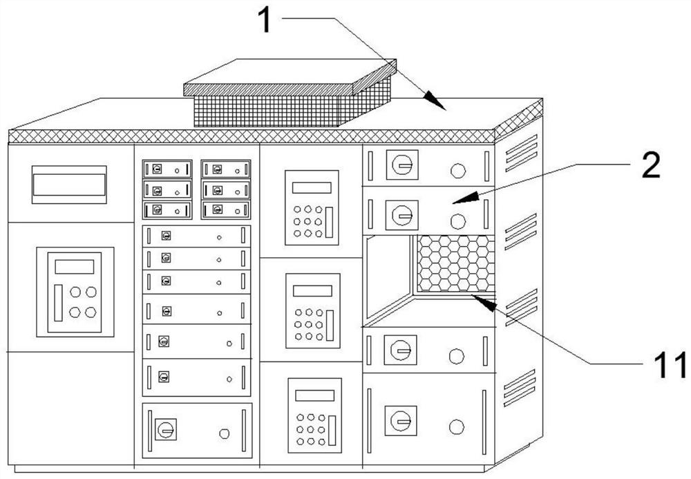
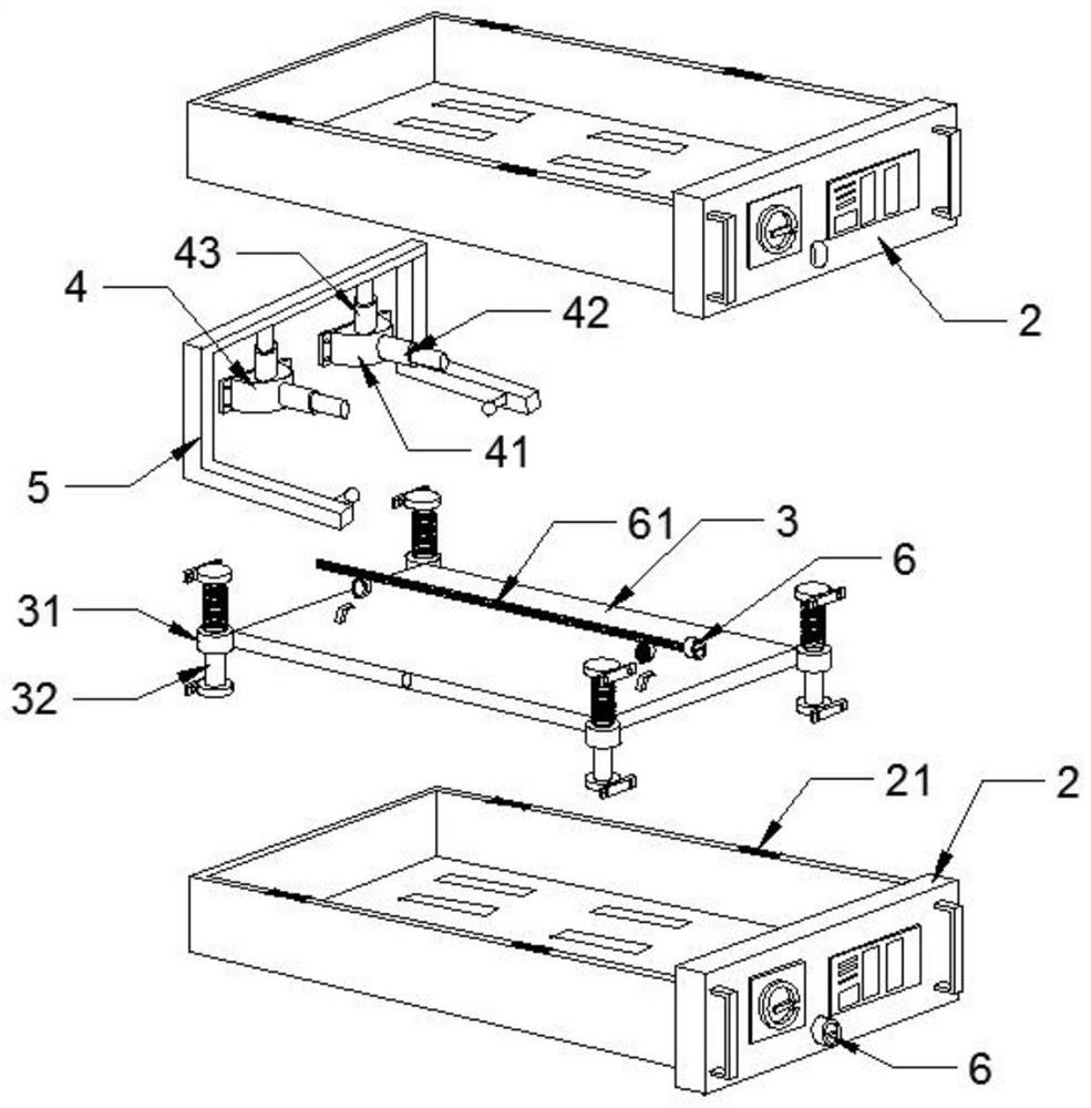
[0034] This embodiment provides a power switch cabinet for digital rural construction, such as figure 1 and figure 2 As shown, it includes a power switch cabinet. Specifically, the switch cabinet includes a housing 1, a modularly designed drawer 2, and a functional unit cavity 11 for accommodating the drawer 2. An isolation barrier is set in the gap between the upper and lower adjacent drawers 2 Board 3, the size of the isolation baffle 3 matches the size of the drawer 2, the four corners of the isolation baffle 3 are provided with connecting collars 31, the connecting collars 31 are sleeved with the vertically arranged lifting columns 32, the top and bottom ends of the lifting columns 32 A fixing foot 321 is provided for connecting with the inner wall of the functional unit cavity 11;

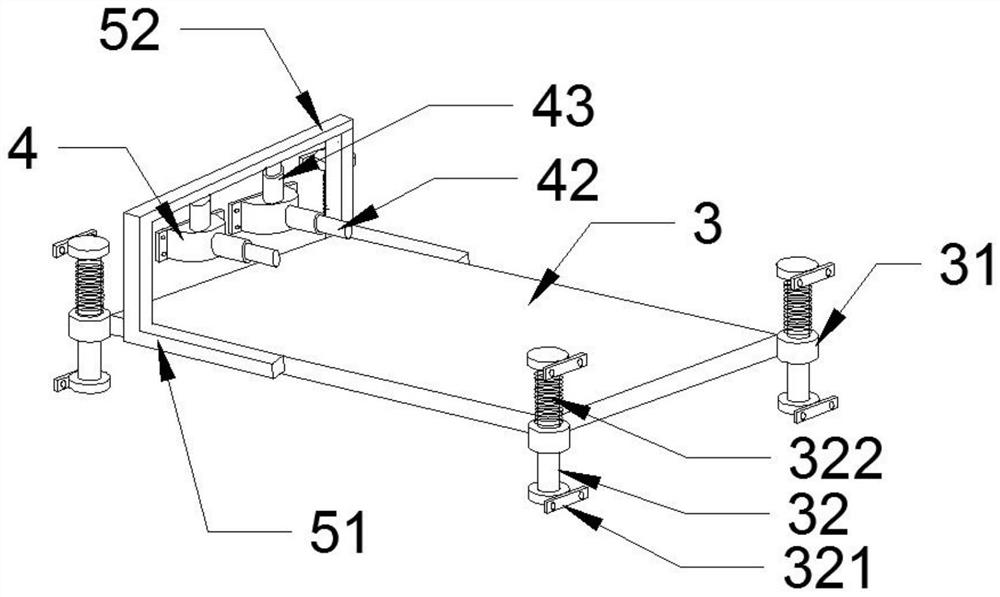
[0035] like image 3 and Figure 5 As shown in the figure, a hydraulic controller 4 is arranged on the cavity wall on the rear side of the functional unit cavity 11. Th...

Example Embodiment

[0047] Example 2

[0048] Based on Example 1 above, see again figure 2 As shown, in Embodiment 2, a plurality of magnetic bodies 21 are uniformly arranged on the top of the side wall of the drawer 2, and the lower surface of the isolation baffle 3 is arranged with a magnetic body 21 which is positioned opposite to it. The function of the magnetic body 21 is that when the isolation baffle 3 is sealed with the lower drawer 2, the combination of the two is tighter, and the sealing effect of the partition wall of the switch cabinet is further improved.


PUM


Abstract

The invention discloses an electric power switch cabinet for digital rural construction, and relates to the technical field of electric power switch cabinets, the electric power switch cabinet comprises a shell, drawers in modular design and a functional unit cavity for accommodating the drawers, an isolation baffle is arranged in a gap between two vertically adjacent drawers, and connecting lantern rings are arranged at four corners of the isolation baffle. The connecting lantern ring is sleeved with a vertically-arranged lifting column, and the top end and the bottom end of the lifting column are provided with fixing feet used for being connected with the inner wall of the functional unit cavity; a hydraulic controller is arranged on the cavity wall of the rear side of the functional unit cavity, an oil cavity of the hydraulic controller is communicated with the driving piston and the driven piston, and the end of the driving piston abuts against the drawer. The end of the driven piston is connected with the isolation baffle through a connecting frame. When the drawer of the switch cabinet is drawn out, the isolation baffle plate can automatically seal the drawer below, and the isolation baffle plate is separated when the drawer is inserted, so that the safety and the heat dissipation performance of the switch cabinet are improved.

Description

technical field [0001] The invention relates to the technical field of power switch cabinets, in particular to a power switch cabinet for digital rural construction. Background technique [0002] The digital village is an endogenous agricultural and rural modernization development and transformation process accompanied by the application of networking, informatization and digitization in the economic and social development of agriculture and rural areas and the improvement of farmers' modern information skills. important content in China. [0003] In the process of digital rural construction, low-voltage switchgear is often used in the power management system. The switchgear is a kind of electrical equipment. The outside line of the switchgear first enters the main control switch in the cabinet, and then enters the sub-control switch, and each branch is required according to its needs. set up. Such as instrumentation, automatic control, motor magnetic switch, various AC co...

Claims


Application Information

Patent Timeline
IPC IPC(8): H02B11/173H02B11/127H02B1/30H02B1/36H02B1/56H02B1/32
CPCH02B11/173H02B11/127H02B1/303H02B1/30H02B1/36H02B1/565H02B1/32H02B1/306
Inventor 李家红朱居友胡军胡艺峰唐玉成商正王腾徐超张成
Owner ANHUI TELECOMM ENG
Why Eureka
Try Eureka