Composite cutter for machining guide pipe hole and seat ring chamfer of aluminum cylinder cover

A conduit hole and composite technology, which is applied in the field of composite cutters for aluminum cylinder head conduit hole and seat ring chamfering, can solve the problem of product quality coaxiality cannot be guaranteed, the cumulative error of secondary repeated positioning, engine cylinder head leakage Air and other problems, to achieve the effect of reducing product scrap loss, improving roundness, and reducing secondary clamping

Pending Publication Date: 2022-08-09
ANHUI HIGH TECH POWER TECH
View PDF0 Cites 0 Cited by
  • Summary
  • Abstract
  • Description
  • Claims
  • Application Information

AI Technical Summary

Problems solved by technology

[0005] ⑴. The two angles of the tool tip are distributed symmetrically at 45 degrees and divided into two parts. There is only a sharp edge of the boring tool, no extruding wiper edge, and the roughness of the hole cannot reach Ra0.8;
[0006] ⑵. Since the chamfering of the seat ring is processed separately after the conduit hole is processed, there is an additional upper and lower clamping, and there is a cumulative error in the positioning of the second repetition. The coaxiality of the product quality cannot be guaranteed, resulting in air leakage of the engine cylinder head under working conditions. Product quality is unstable and affects work efficiency

Method used


Image

  • Composite cutter for machining guide pipe hole and seat ring chamfer of aluminum cylinder cover
  • Composite cutter for machining guide pipe hole and seat ring chamfer of aluminum cylinder cover
  • Composite cutter for machining guide pipe hole and seat ring chamfer of aluminum cylinder cover

Examples


Embodiment Construction

[0028] In order to make the objectives, technical solutions and advantages of the present invention clearer, the present invention will be further described in detail below with reference to the embodiments. It should be understood that the specific embodiments described herein are only used to explain the present invention, but not to limit the present invention.

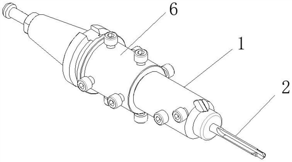
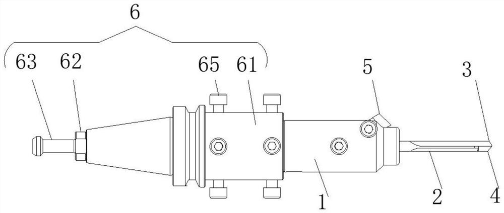
[0029] like figure 2 and image 3 As shown in the figure, a composite tool for chamfering a conduit hole of an aluminum cylinder head and a seat ring includes a main tool bar 1, and one end of the main tool bar 1 is provided with a fine boring and fine reaming compound tool 2. The fine boring and fine reaming compound tool 2. A fine boring cutter edge 3 and a fine reamer cutter edge 4 are respectively provided on both sides of one end away from the main cutter bar 1, and the lateral distance between the tool tip of the fine boring cutter edge 3 and the main cutter bar 1 is greater than that of the fine reamer cut...


PUM


Abstract

A composite cutter for machining a guide pipe hole and a seat ring chamfer of an aluminum cylinder cover comprises a main cutter rod, a fine boring and fine reaming composite cutter is arranged at one end of the main cutter rod, and a fine boring blade and a fine reaming blade are arranged on the two sides of the end, away from the main cutter rod, of the fine boring and fine reaming composite cutter respectively. The transverse distance between a tool nose of the fine boring tool edge and the main tool bar is larger than that between a tool nose of the fine reaming tool edge and the main tool bar, the fine boring tool edge is made to feed before the fine reaming tool edge, and a seat ring chamfering tool is installed on the outer surface of the end, facing the fine boring and fine reaming composite tool, of the main tool bar. A fine boring blade of the fine boring and fine reaming compound cutter is fed in the front, a fine reaming blade of the fine boring and fine reaming compound cutter is fed in the rear, boring and reaming are combined, the roundness of a hole is improved, after a boring and reaming guide pipe hole cutter point goes out of the hole, a seat ring chamfering cutter chamfers a cylinder cover seat ring orifice by 0.8 * 45 degrees, one-time machining forming is achieved, secondary clamping is reduced, repeated positioning and accumulative errors are reduced, and the machining efficiency is improved. And the coaxial precision of the guide pipe hole and the seat ring chamfer is improved.

Description

technical field [0001] The invention belongs to the technical field of cutting tools, and particularly relates to a composite cutting tool for chamfering a conduit hole and a seat ring of an aluminum cylinder head. Background technique [0002] The aluminum cylinder head is one of the key components of the four-stroke internal combustion engine. The parts installed on the cylinder constitute the position of the valve stem, the combustion chamber, the camshaft and the rocker shaft support. And install the important components of the cylinder head of the intake, exhaust valve and injector assembly, conduct the room temperature in the cylinder, and realize the cylinder block assembly with the functions of heat storage and heat dissipation. The aluminum cylinder head is mainly a part with a relatively concentrated hole system. The intake and exhaust valves mainly form an open loop and a closed loop during the working process, while the two conduit holes on the base of the cylind...

Claims


Application Information

Patent Timeline
Patent Type & Authority Applications(China)
IPC IPC(8): B23B27/00B23D77/00
CPCB23B27/00B23D77/00Y02T10/12
Inventor 占长安章高伟
Owner ANHUI HIGH TECH POWER TECH
Why Eureka
Try Eureka