River sewage treatment equipment with sludge residue storage treatment function
A kind of sewage treatment equipment and sludge technology, which is applied in the direction of water/sludge/sewage treatment, sludge treatment, dehydration/drying/concentrated sludge treatment, etc., and can solve filter clogging, insufficient sludge suction, impact Sewage treatment efficiency and other issues, to achieve the effect of low cost and ingenious structural design
- Summary
- Abstract
- Description
- Claims
- Application Information
AI Technical Summary
Problems solved by technology
Method used
Image
Examples
Embodiment 1
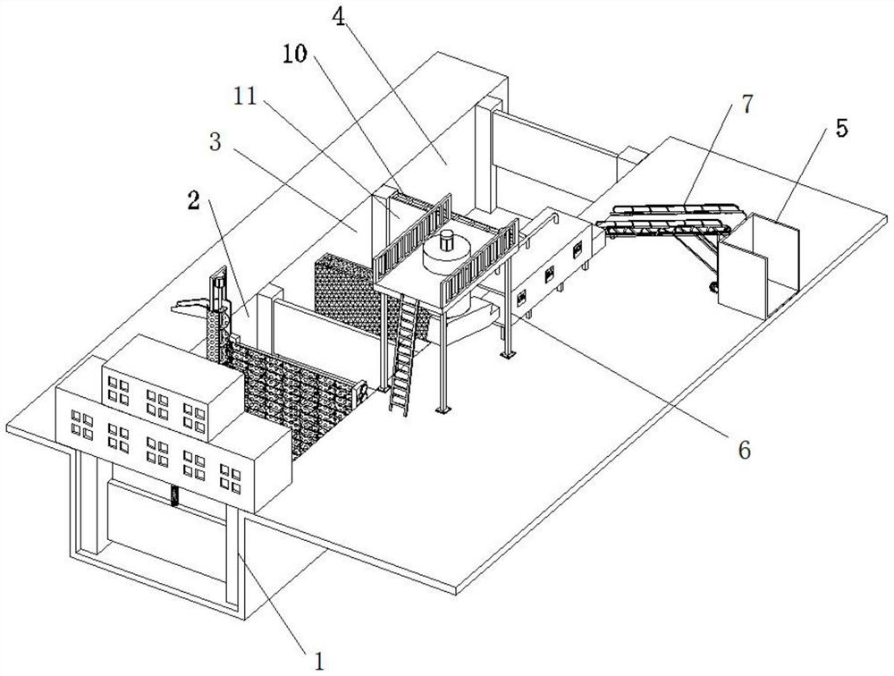
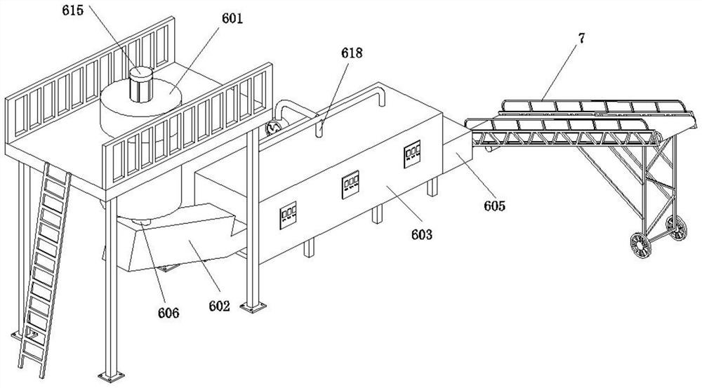
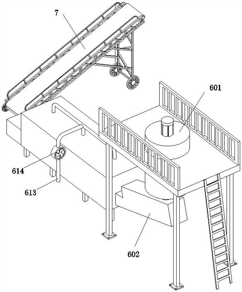
[0042] An embodiment provided by the present invention: a river sewage treatment equipment with sludge residue storage and treatment, please refer to figure 1 and figure 2 , including the sluice 1, the aeration tank 2, the biochemical tank 3, the discharge tank 4 and the recovery tank 5, the sluice 1, the aeration tank 2, the biochemical tank 3, and the discharge tank 4 are installed on the river from left to right. The flow direction also passes through the sluice 1, the aeration tank 2, the biochemical tank 3 and the discharge tank 4 in sequence. The sludge at the bottom of the aeration tank 2 is sucked by the strong self-priming mud pump 9 to the sludge crushing and drying device 6, and the sludge crushing and drying device 6 The discharge port is connected with a belt conveyor 7, and the discharge end of the belt conveyor 7 is set above the recovery tank 5, and the recovery tank 5 is mainly used to accumulate and recover the solidified sludge; the connection between the b...
Embodiment 2
[0049] On the basis of Example 1, see Figure 7 and Figure 8 , between the front bearing frame 201 and the rear bearing frame 203 is also provided with a self-reversing reciprocating device 8. The self-reversing reciprocating device 8 includes a double-slotted screw 801, a guide rail frame 802, a moving seat 803 and a second driven gear 804. The outer wall of the grooved screw 801 is connected with a nut 805. The left end of the nut 805 is connected with the guide rail frame 802 through the slider 806. The right end of the nut 805 is fixed with a movable seat 803. The gun head 807 is connected to the powerful self-priming mud pump 9 through a mud suction hose 808, and the output end of the self-priming mud pump 9 is connected with a mud outlet pipe 809; the bottom first driven gear 206 and the second driven gear 804 Mesh connection. The outer wall of the double-grooved screw 801 is provided with two staggered spiral grooves. The double-grooved screw 801 is rotatably install...
PUM
 Abstract
Description
Claims
Application Information
 - R&D
- Intellectual Property
- Life Sciences
- Materials
- Tech Scout
- Unparalleled Data Quality
- Higher Quality Content
- 60% Fewer Hallucinations
Browse by: Latest US Patents, China's latest patents, Technical Efficacy Thesaurus, Application Domain, Technology Topic, Popular Technical Reports.
© 2025 PatSnap. All rights reserved.Legal|Privacy policy|Modern Slavery Act Transparency Statement|Sitemap|About US| Contact US: help@patsnap.com


