Separation equipment for preventing sludge blockage in sewage treatment

A technology for sewage treatment and separation equipment, which is applied in water/sludge/sewage treatment, sludge treatment, sustainable biological treatment, etc. It can solve the problem that the differential feed compression and sludge discharge cannot be realized, and the centrifugal separation effect cannot be guaranteed. , It is impossible to realize the problems of linkage vibration and water removal, so as to achieve the effect of improving the overall practicability, the overall structure is simple and stable, and the structure is simple and practical.

Pending Publication Date: 2022-08-09
邓瑞亮
View PDF18 Cites 0 Cited by
  • Summary
  • Abstract
  • Description
  • Claims
  • Application Information

AI Technical Summary

Problems solved by technology

[0003] However, as far as the separation equipment for traditional sewage treatment to prevent sludge clogging is concerned, it is impossible to achieve differential feed compression and sludge discharge, which is not practical enough, and the water removal efficiency is low. At the same time, the centrifugal separation effect cannot be guaranteed, and the overall linkage is poor. Self-cleaning cannot be realized, manual cleaning is required at regular intervals, and at the same time, linkage vibration and water removal cannot be realized, which affects the separation efficiency and the overall separation process effect is poor

Method used


Image

  • Separation equipment for preventing sludge blockage in sewage treatment
  • Separation equipment for preventing sludge blockage in sewage treatment
  • Separation equipment for preventing sludge blockage in sewage treatment

Examples


Embodiment 1

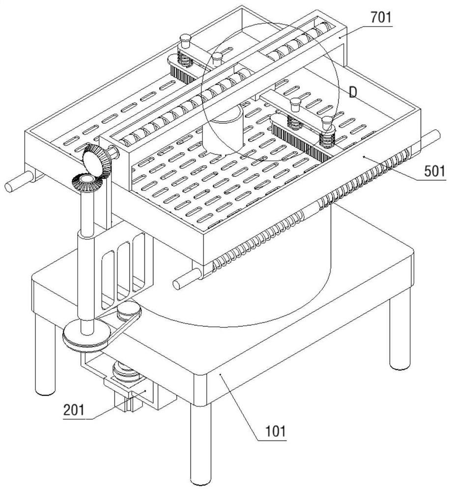
[0040] Please refer to Figure 1 to Figure 13 :

[0041] The invention proposes a separation device for preventing sludge clogging for sewage treatment, which includes an installation support part 1; a differential drive device 2 is fixedly connected to the installation support part 1; a terminal filter part 3 is rotatably connected to the installation support part 1; The conveying device 4 is installed on the part 3; the movable bearing part 5 is slidably connected to the installation support part 1; the extrusion linkage part 6 is slidably connected to the installation support part 1; The cleaning device 8 is installed on the sliding reciprocating drive part 7; the installation support part 1 includes: an installation support plate 101, a support leg 102, a protective installation cylinder 103, a water outlet pipe 104 and a rotating shaft frame 105. The bottom of the installation support plate 101 is fixedly connected with four A protective installation cylinder 103 is fixe...

Embodiment 2

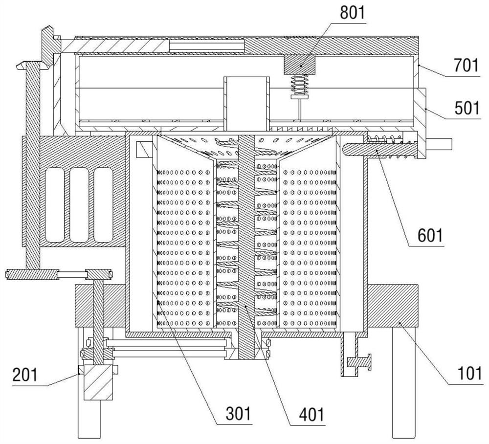
[0044] like Figure 8 to Figure 10 As shown, the conveying device 4 includes: a conveying auger 401 and a conveying pulley 402, the conveying auger 401 is rotatably connected to the centrifugal mesh cylinder 301; the bottom of the conveying auger 401 is fixedly connected with a conveying pulley 402, and the conveying pulley 402 passes through The belt drive is connected to the conveying drive pulley 203; the conveying device 4 also includes: a conveying isolation cylinder 403 and a collecting mesh ring 404, the conveying isolation cylinder 403 is fixedly connected inside the centrifugal mesh cylinder 301; the conveying isolation cylinder 403 is provided with filter holes; The isolation cylinder 403 is fixedly connected with a collection screen ring 404, and the collection screen ring 404 is provided with filter holes; the moving bearing part 5 includes: a moving box 501, a sliding drive shaft 5011, a return spring 502, a lower filter screen 503, and a collection isolation scree...

Embodiment 3

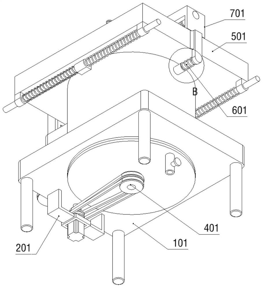
[0046] like Figure 11 to Figure 13 As shown, the sliding reciprocating drive part 7 includes: a sliding support 701, a reciprocating screw 702, a driving sliding shaft 703, a cleaning drive bevel gear 704 and a gear frame 7041, and the sliding support 701 is fixedly connected to the moving box 501; the sliding support A reciprocating screw 702 is rotatably connected to the reciprocating screw 701, and a hexagonal hole is formed on the reciprocating screw 702; the reciprocating screw 702 is provided with a bidirectional thread; the reciprocating screw 702 is slidably connected with a driving sliding shaft 703, and the driving sliding shaft 703 has a hexagonal structure; the driving sliding shaft 703 is fixedly connected with a cleaning and driving bevel gear 704; the cleaning and driving bevel gear 704 is engaged with the transmission bevel gear 108; 7041 is fixedly connected to the rotating shaft frame 105; the cleaning device 8 includes: a cleaning sliding frame 801, a mount...


PUM


Abstract

The invention provides separation equipment for preventing sludge blockage for sewage treatment, and relates to the technical field of sewage treatment. A differential driving device is fixedly connected to the mounting supporting part; the mounting supporting part is rotationally connected with a terminal filtering part; a conveying device is mounted on the terminal filtering part; a movable bearing part is connected to the mounting supporting part in a sliding manner; an extrusion linkage part is connected to the mounting supporting part in a sliding manner; the movable bearing part is fixedly connected with a sliding reciprocating driving part; a cleaning device is mounted on the sliding reciprocating driving part; differential cutter suction and discharging work can be achieved, vibration accelerated separation can be achieved in an auxiliary mode, and the overall separation efficiency is higher; the problems that according to existing traditional separation equipment for preventing sludge blockage for sewage treatment, differential feeding compression and sludge discharging work cannot be achieved, practicability is not enough, the water removal efficiency is low, and meanwhile the centrifugal separation effect cannot be guaranteed are solved.

Description

technical field [0001] The invention relates to the technical field of sewage treatment, in particular to a separation device for preventing sludge clogging for sewage treatment. Background technique [0002] Sewage treatment is the process of purifying sewage so that it can meet the water quality requirements for discharge into a water body or for reuse. Sewage treatment is widely used in construction, agriculture, transportation, energy, petrochemical, environmental protection, urban landscape, medical, catering and other fields. In the actual sewage treatment process, sludge is a very common form. At this time, a good It is particularly important to use separation equipment for sewage treatment to prevent sludge clogging. [0003] However, as far as the current separation equipment used for traditional sewage treatment to prevent sludge clogging is concerned, it is impossible to achieve differential feed compression and sludge discharge, which is not practical, has low w...

Claims


Application Information

Patent Timeline
Patent Type & Authority Applications(China)
IPC IPC(8): C02F11/127C02F11/122
CPCC02F11/127C02F11/122C02F2303/14C02F2303/16Y02W10/10
Inventor 邓瑞亮
Owner 邓瑞亮
Why Eureka
Try Eureka