
Tantalum capacitor automatic detection device
An automatic detection device, tantalum capacitor technology, applied in the direction of measurement device, capacitor test, measurement device shell, etc., can solve the problems of time-consuming, laborious, low efficiency, etc., to prevent damage, reduce burden, and facilitate compact layout.
- Summary
- Abstract
- Description
- Claims
- Application Information
AI Technical Summary
Problems solved by technology
Method used
Image

Examples
Embodiment 1
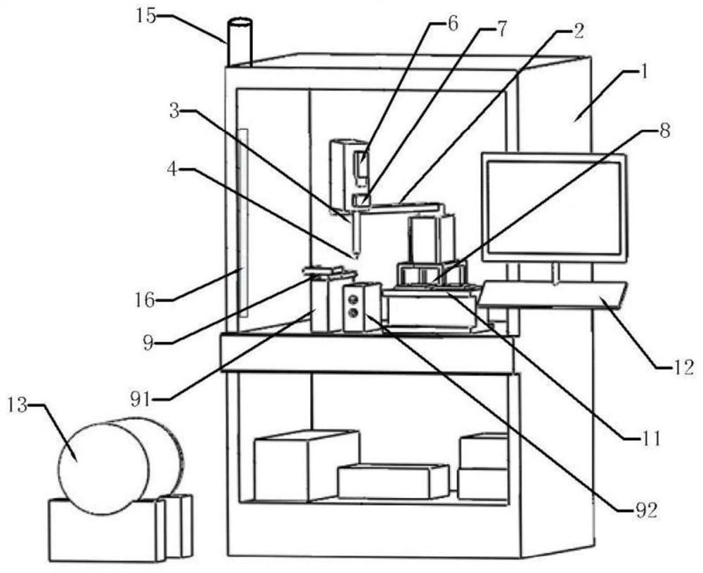
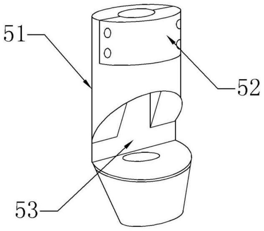
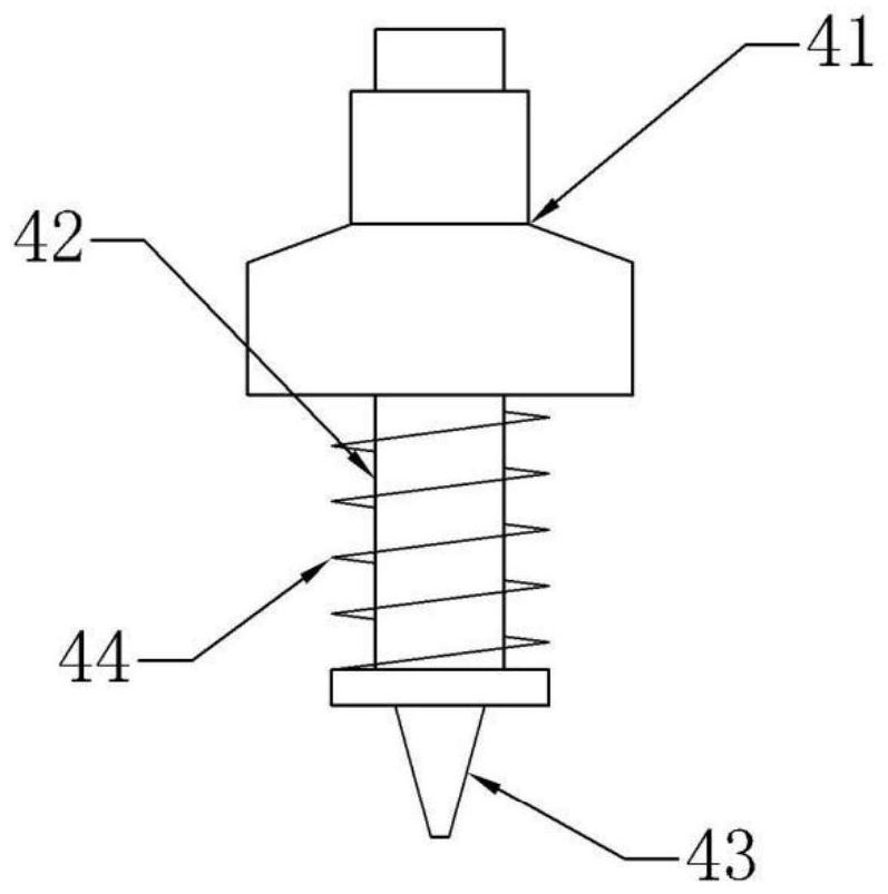
[0033] like Figure 1-7 As shown, an automatic detection device for tantalum capacitors includes a frame 1, a manipulator 2, a lifting mechanism 3, a suction nozzle 4, a suction nozzle fixing bracket 5, an industrial camera 6, a light source 7, a test table 8, a feeding tray 9, a feeding trough 10. Discharge tray 11, controller 12, negative pressure source 13, vacuum gauge 14 and alarm 15; the manipulator 2, lifting mechanism 3, industrial camera 6, light source 7, negative pressure source 13, testing instrument, feeding tray 9. The vacuum gauge 14 and the alarm 15 are electrically connected to the controller 12 .
[0034]The rack 1 has a double-layer cabinet structure with an open front. The feeding tray 9 , the manipulator 2 , the test table 8 and the unloading tray 11 are sequentially installed on the upper table of the rack 1 . The manipulator 2 includes a primary mechanical arm 21, a secondary mechanical arm 22, a primary driving member 23 and a secondary driving member ...
PUM
 Abstract
Description
Claims
Application Information