Module capacity measurement system and module capacity measurement method

A measurement system and capacity test technology, applied in the direction of measuring electrical variables, measuring electricity, measuring devices, etc., can solve the problems of module test compatibility and low test efficiency, prone to subjective errors, relying on manual operation, etc., to improve safety Sex and efficiency, lower quality requirements, fast and compatible effects

Pending Publication Date: 2022-08-09
BATTERO TECH CORP LTD
View PDF0 Cites 0 Cited by
  • Summary
  • Abstract
  • Description
  • Claims
  • Application Information

AI Technical Summary

Problems solved by technology

[0004] The technical problem to be solved by the present invention is that the existing module test series connection process relies too much on manual operation, which is prone to subjective errors and property losses, and the existing module test compatibility and test efficiency are relatively low

Method used


Image

  • Module capacity measurement system and module capacity measurement method
  • Module capacity measurement system and module capacity measurement method

Examples


Embodiment 1

[0039] In order to solve the technical problems existing in the prior art, an embodiment of the present invention provides a module capacity measurement system.

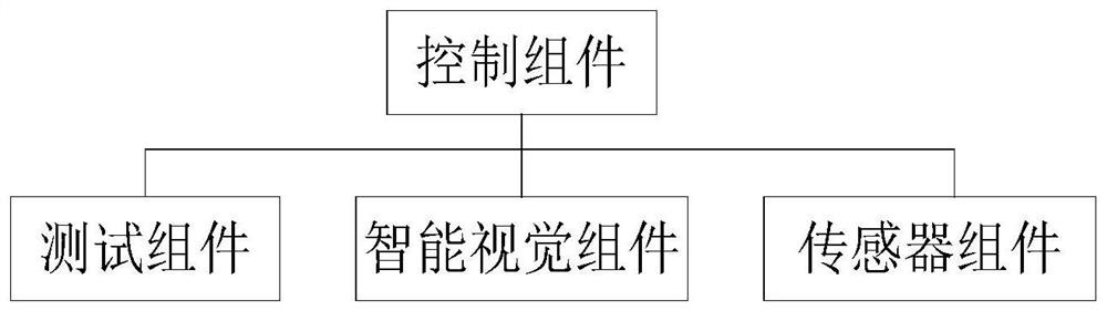
[0040] figure 1 A schematic structural diagram of a module capacity measurement system according to an embodiment of the present invention is shown; refer to figure 1 As shown, the module capacity measurement system according to the embodiment of the present invention includes a test component, an intelligent vision component, a sensor component and a control component, wherein the control component is respectively connected to the pre-test component, the intelligent vision component and the sensor component.

[0041] Among them, the test component is mainly used to fix the module to be tested during the module capacity measurement process, and in the measurement stage, based on the charge-discharge control signal, the capacity test is performed on the module to be tested that has been connected in series to obtain c...

Embodiment 2

[0059] In order to solve the technical problems existing in the prior art, an embodiment of the present invention provides a method for measuring the capacity of a module. The module capacity measurement method in this embodiment is implemented on the basis of the module capacity measurement system disclosed in the first embodiment.

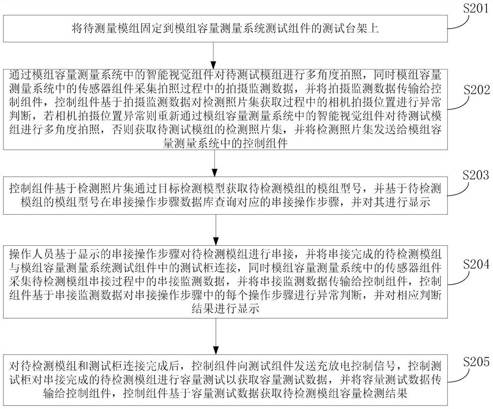
[0060] figure 2 A schematic flowchart of the method for measuring the capacity of a module according to the second embodiment of the present invention is shown. Referring to Embodiment 2, the method for measuring the capacity of a module according to an embodiment of the present invention includes the following steps.

[0061] In step S201, the module to be measured is fixed on the test bench of the test component of the module capacity measurement system.

[0062] Specifically, the module to be tested is fixed on the test bench of the test component in the module capacity measurement system by the fixing member on the test bench.

[0063] St...


PUM


Abstract

The invention discloses a module capacity measurement system and a module capacity measurement method, and the system comprises a test assembly which is used for fixing modules to be detected, carrying out the capacity test of the serially connected modules to be detected to obtain capacity test data, and transmitting the capacity test data to a control assembly; the intelligent visual component is used for acquiring a detection photo set of a to-be-detected module and transmitting the detection photo set to the control component; the sensor assembly is arranged on the test assembly and is used for collecting serial connection monitoring data, shooting monitoring data and module temperature data and transmitting the monitoring data to the control assembly; and the control assembly is used for processing and displaying various data and sending a charging and discharging control signal to the test assembly. According to the invention, the operation error of personnel can be effectively reduced, the requirement on the quality of operators is reduced, meanwhile, different module tests can be rapidly compatible, the dynamic monitoring of the whole test process is realized, and the safety and efficiency of the module capacity test are also greatly improved.

Description

technical field [0001] The invention relates to the technical field of battery module detection, in particular to a module capacity measurement system and a module capacity measurement method. Background technique [0002] Module capacity testing is an important part of new energy manufacturing. Due to the different internal structures of battery bundled boxes of various manufacturers, the styles of their internal modules are also very different; for factories, this kind of small batch of various types of modules Group capacity test, installation inspection and process monitoring can only be carried out by manual installation and manual inspection, which requires higher professional quality for operators. [0003] Existing modules have many types and styles, and most of the installation positions are different. The existing capacity testing method requires operators to frequently memorize the installation positions, so it has certain technical difficulties. Further, the exi...

Claims


Application Information

Patent Timeline
IPC IPC(8): G06F16/9032G06F16/9038G06F16/583G06V10/764G06V10/774G06T7/70G06Q50/04G01R31/387G01R31/396
CPCG06F16/9032G06F16/9038G06F16/583G06V10/764G06V10/774G06T7/70G06Q50/04G01R31/387G01R31/396G06V2201/06G06T2207/30244Y02E60/10
Inventor 岳新杰孙晓雁李坤
Owner BATTERO TECH CORP LTD
Why Eureka
Try Eureka