Eureka AIR delivers breakthrough ideas for toughest innovation challenges, trusted by R&D personnel around the world.

DC electric motor

A DC motor, magnetic pole technology, applied in the manufacture of motor generators, motor components, DC commutators, etc., can solve the problems of uneven tension, inability to obtain torque performance, uneven coil winding, etc., to achieve uniform winding, reduce Cogging torque and the effect of approximately uniform length of transition line

Inactive Publication Date: 2004-05-12
KK TOSHIBA
View PDF0 Cites 3 Cited by
  • Summary
  • Abstract
  • Description
  • Claims
  • Application Information

AI Technical Summary

Problems solved by technology

Therefore, the tension of the winding between the T-shaped magnetic poles is not uniform, and the coil is not evenly wound.
At the same time, the extension of the coils between the T-shaped magnetic poles is different, and the resistance value of the coils between the T-shaped magnetic poles is also different, which may not be able to obtain stable torque performance.

Method used


Image

  • DC electric motor
  • DC electric motor
  • DC electric motor

Examples


Embodiment Construction

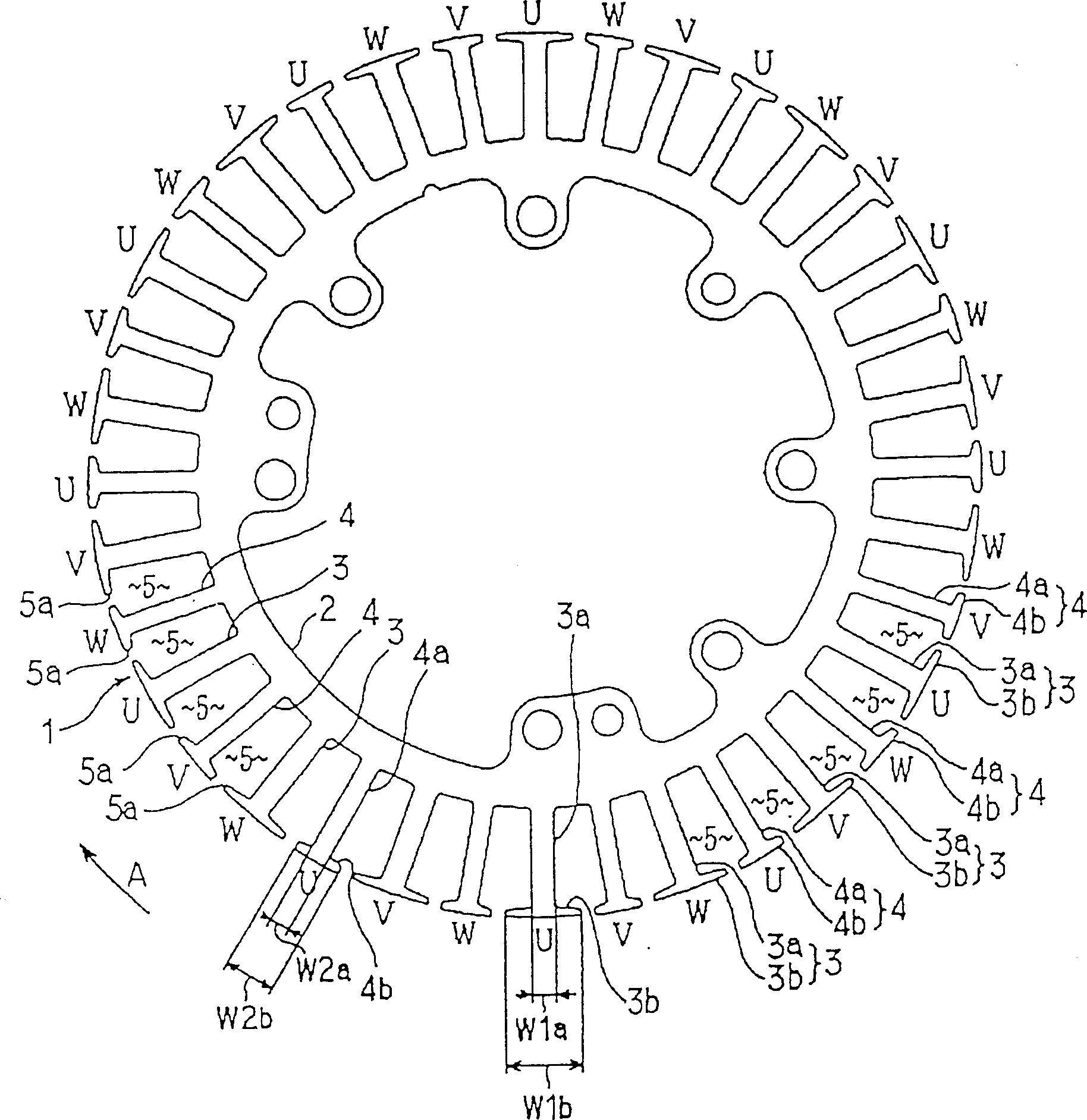
[0038] Next, an embodiment of the present invention will be described with reference to the drawings. This embodiment adopts the present invention as an outer rotor type 3-phase 36-pole DC brushless motor for driving a washing machine pulsator and a washing tub.

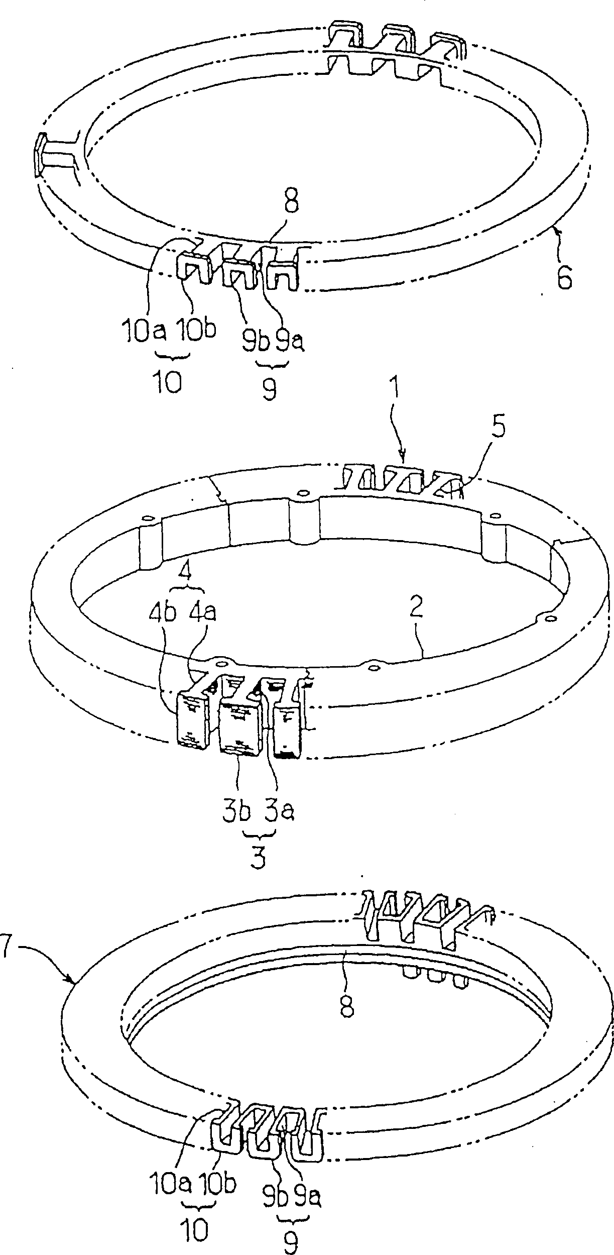
[0039] First, in figure 1Among them, the stator core 1 is composed of a substantially cylindrical inner yoke 2, 18 first T-shaped magnetic poles 3 radially extending from the inner yoke 2, and 18 second T-shaped magnetic poles 4 radially extending from the inner yoke 2 The configuration is such that the first T-shaped magnetic poles 3 and the second T-shaped magnetic poles 4 are alternately arranged at equal pitches (=10°) along the circumferential direction.

[0040] Each first T-shaped magnetic pole 3 is made up of a square column-shaped coil winding portion 3a and a magnetic pole portion 3b protruding from the side of the coil winding portion 3a in the circumferential direction. The circumferential width dimensio...


PUM


Abstract

The invention provides a DC motor which can significantly reduce cogging torque and yet wind coils in balance. A stator core 1 has alternately arranged first magnetic pole teeth 3 and second magnetic pole teeth 4. Magnetic pole sections 3b, large in width in the circumferential direction, and magnetic pole section 4b, small in width in the circumferential direction, are formed at the tips of the magnetic pole teeth 3, 4. Coils in phases U-W are continuously wound around the first magnetic pole teeth 3 and the second magnetic pole teeth 4 alternately, and the length of each cross-over line is almost uniform regardless of the width of the magnetic pole teeth 3, 4.

Description

technical field [0001] The present invention relates to a direct current motor having two types of T-shaped magnetic poles having different widths in the circumferential direction from opposing rotor magnetic pole parts or stator magnetic pole parts. Background technique [0002] For example, some outer-rotor type 3-phase DC brushless motors have protruding magnetic poles on the side of the T-shaped magnetic poles in the circumferential direction, so that the openings of the slots are half-closed. With this structure, since the rotor magnet faces the opening of the slot, the moment when the magnet is not affected by the magnetic flux is reduced, so the cogging torque becomes small and the rotor runs smoothly. [0003] In the above-mentioned DC motor, it is conceivable to alternately change the circumferential dimension of the magnetic pole portion so that the positions of the slot openings alternately change in the circumferential direction. With such a structure, the momen...

Claims


Application Information

Patent Timeline
Patent Type & Authority Patents(China)
IPC IPC(8): H02K1/14H02K1/27H02K3/18H02K3/28H02K3/52H02K15/095H02K23/26H02K23/40H02K29/00H02K29/03
CPCH02K3/28H02K2203/06H02K1/2786H02K23/26H02K15/095H02K29/03H02K3/522H02K23/40H02K3/18H02K2203/12H02K1/2791H02K21/22
Inventor 长崎康昌堀田英雄北村一夫
Owner KK TOSHIBA
Why Eureka
Eureka Blog
Learn More