Supercharge Your Innovation With Domain-Expert AI Agents!

Power amplifier

A technology of power amplifier and power amplification, which is applied in the direction of power amplifiers, amplifiers, amplifier combinations, etc., can solve problems such as oversize, and achieve the effects of efficiency improvement, circuit simplification, and volume reduction

Inactive Publication Date: 2004-08-11
LENOVO INNOVATIONS LTD HONG KONG
View PDF3 Cites 0 Cited by
  • Summary
  • Abstract
  • Description
  • Claims
  • Application Information

AI Technical Summary

Problems solved by technology

[0007] Therefore, devices using such power amplifiers become overly large
It is disadvantageous to use such a power amplifier in, for example, a portable telephone where space is limited and size reduction is required

Method used


Image

  • Power amplifier
  • Power amplifier
  • Power amplifier

Examples


Embodiment Construction

[0036] Preferred embodiments according to the present invention are described below with reference to the accompanying drawings.

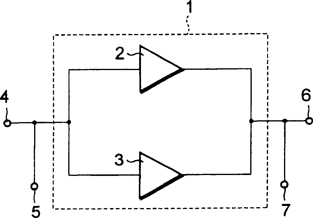
[0037] figure 1 is a structural block diagram of the power amplifier according to the first embodiment of the present invention. In this embodiment, a power amplifier including a field effect transistor is described.

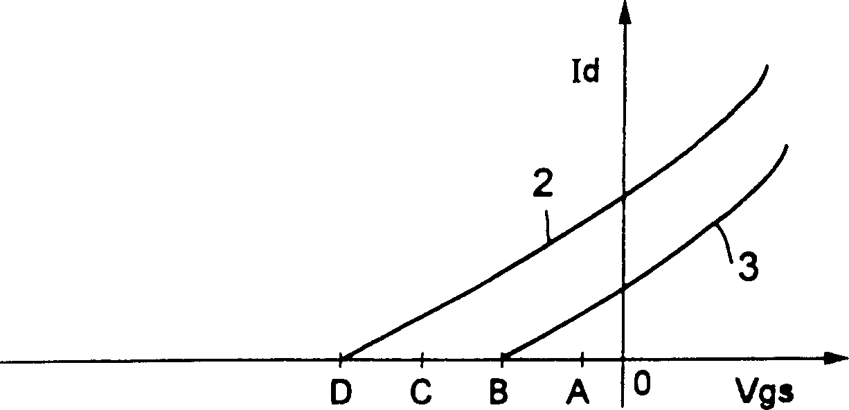
[0038] figure 1The power amplifier 1 of the present embodiment shown is composed of transistor units 2 and 3 connected in parallel. Each transistor unit 2 and 3 comprises at least one field effect transistor. Its electrostatic properties, ie the cut-off voltage of transistor unit 2 in the selected example, differ from the electrostatic properties of transistor unit 3 .

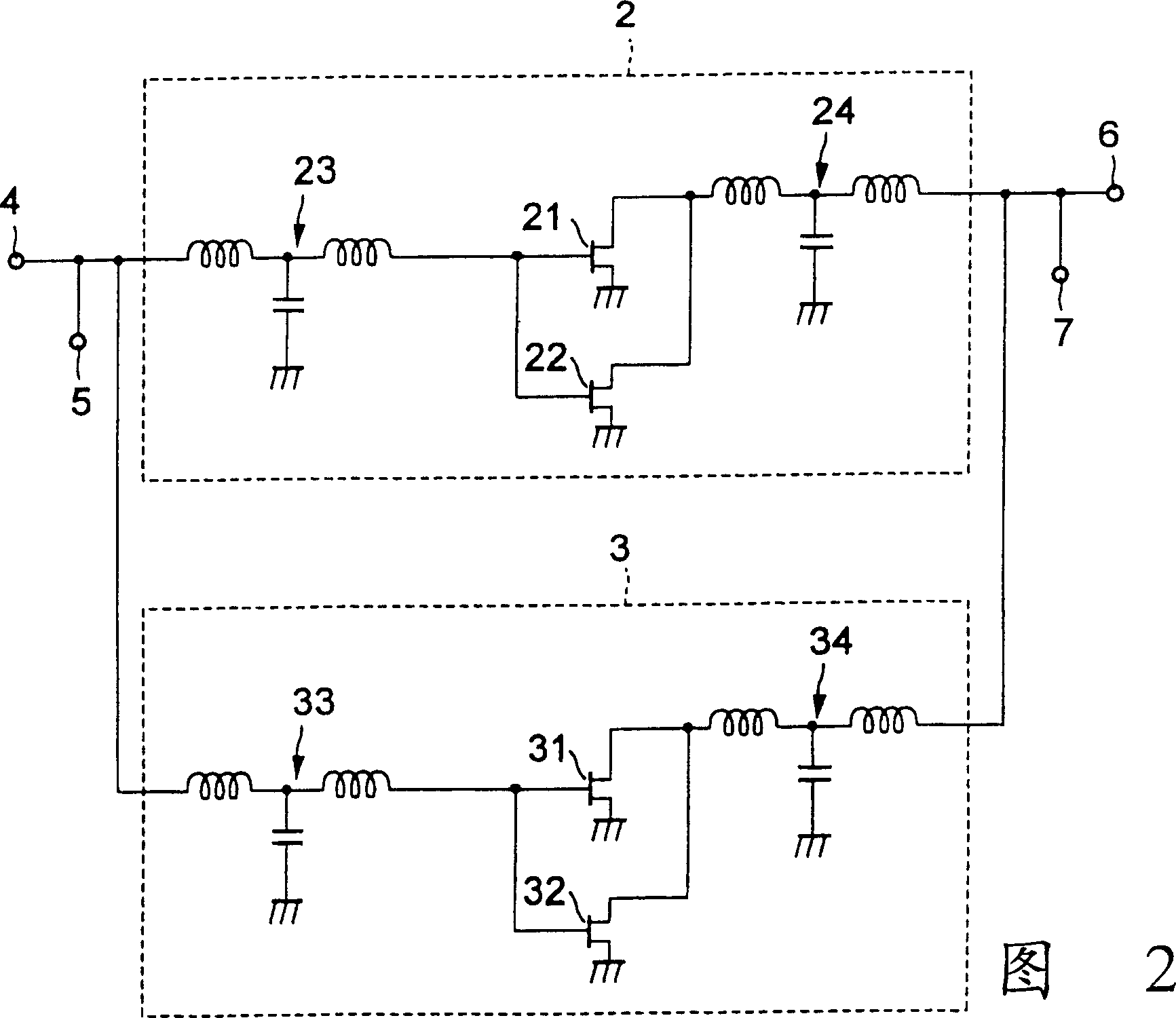
[0039] Figure 2 is figure 1 Circuit diagram of the internal structure of transistor cells 2 and 3 shown. Transistor cells 2 and 3 each include two field effect transistors.

[0040] In the transistor unit 2, the input terminals and the output terminals of the ...


PUM


Abstract

In a power amplifier for amplifying power using a transistor, the transistor includes a plurality of transistor units connected in parallel and having different static characteristics or pinch-off voltages. When a bias voltage applied to the plurality of transistor units is lowered, predetermined transistor units of the plurality of transistor units are turned off by pinch-off, and the remaining transistor units are in an ON state.

Description

technical field [0001] The present invention relates to a power amplifier, and more particularly, to an amplifier in which transistors having a new structure are used to achieve downsizing without lowering efficiency in low output modes. Background technique [0002] Generally, when a radio frequency device transmits a radio frequency signal, the transmitted signal is amplified by a power amplifier and output with a set power. For such power amplifiers, lower power consumption and higher efficiency are required. [0003] As a commonly used amplifier with low power consumption, Japanese Unexamined Patent Publication No. 1-117405 discloses an operational amplifier, Japanese Unexamined Patent Publication No. 5-243862 discloses a field effect transistor amplifier circuit, and Japanese Unexamined Patent Publication No. No. 7-202595 discloses an inverting amplifier. [0004] Generally, when using such commonly used power amplifiers and continuously changing their output, the mag...

Claims


Application Information

Patent Timeline
IPC IPC(8): H03F3/68H03F3/21H04B1/3822H04B1/40
CPCH03F3/211H03F3/72
Inventor 乘松秀彦
Owner LENOVO INNOVATIONS LTD HONG KONG
Features
  • R&D
  • Intellectual Property
  • Life Sciences
  • Materials
  • Tech Scout
  • Unparalleled Data Quality
  • Higher Quality Content
  • 60% Fewer Hallucinations
Learn More