
Semiconductor side pumping solid laser gyroscope and its electrooptical modulation method

A side-pumped, solid-state laser technology, applied in the direction of steering sensing equipment, etc., can solve the problems of difficult miniaturization, low overall efficiency, system noise, etc., achieve similar mechanical jitter, improve measurement accuracy, and overcome thermal stress effects

Inactive Publication Date: 2004-08-18
TSINGHUA UNIV
View PDF0 Cites 0 Cited by
  • Summary
  • Abstract
  • Description
  • Claims
  • Application Information

AI Technical Summary

Problems solved by technology

Although the gas laser gyroscope is the most accurate among the current optical gyroscopes, it has its inherent disadvantages: ①The gain medium of the gas laser gyroscope is He-Ne mixed gas. In order to ensure the constant gas composition and concentration, it needs to be replaced frequently. Inflatable gas, so the sealing of the cavity is very high; ②The gain is a mixed gas, in order to ensure the oscillation condition, the gas gain must have a certain limit optical path, that is, the cavity is difficult to miniaturize, and the gas discharge requires high voltage; ③He-Ne The working laser wavelength of the gas laser gyroscope is relatively short (633nm), so the coating process of the reflector of the ring resonator is very demanding, which greatly increases the cost; ④ In order to eliminate the inherent lock-up, the gas laser gyroscope introduces a mechanical The additional components of the jitter not only increase the complexity of the gyro system, but also bring additional noise to the system; ⑤The total efficiency is very low, less than <0.01%
The disadvantage is that due to the semiconductor end-pumping method, it is difficult to further miniaturize the annular cavity, and because the end-pumping inevitably uses an 8-shaped cavity, there is a negative area, and the calibration factor of the gyroscope will be reduced. At the same time, the end-pumping method will Uneven thermal stress that causes crystal gain reduces gyroscope life and requires more optical components and complex structure

Method used


Image

  • Semiconductor side pumping solid laser gyroscope and its electrooptical modulation method
  • Semiconductor side pumping solid laser gyroscope and its electrooptical modulation method
  • Semiconductor side pumping solid laser gyroscope and its electrooptical modulation method

Examples


Embodiment

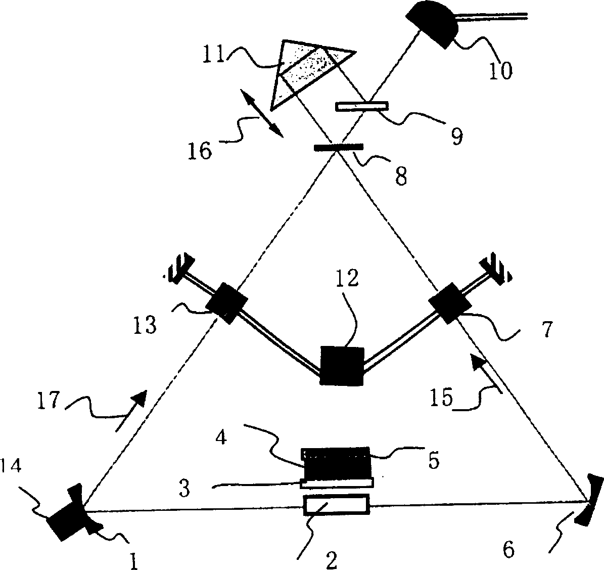
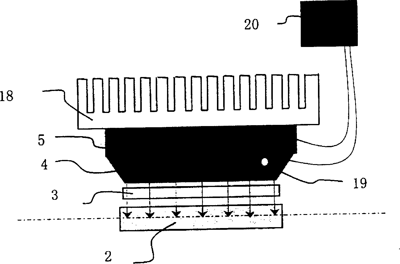
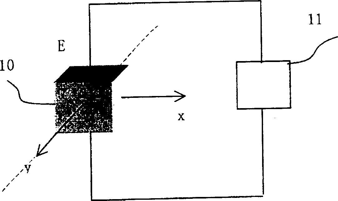
[0031] Embodiment: the structural representation of this system is as figure 1 shown. The detailed steps are as follows: the semiconductor laser array 4 used is a 6W GaAlAs / GaAs double heterojunction laser array with a peak wavelength of 810±5nm, fixed on a semiconductor refrigerator, and controlled by a temperature control system. Gain medium 2 uses a crystal whose absorption wavelength matches the peak wavelength of the semiconductor laser. We choose a very mature Nd:YVO 4 , Nd:YAG was not selected. Nd:YVO 4 The doping concentration of the crystal is ≈0.5%, the geometric shape is a slab, and the size is 10×5×5mm. The input and output end faces (that is, two 5×5mm faces) are coated with a high-transparency film with a reflectivity of no higher than 0.1% for 1064nm wavelength. The side away from the cylindrical lens is coated with a high-reflection film with a reflectance of no less than 98% for a wavelength of 1064nm, and the side close to the cylindrical lens is coated w...


PUM


Abstract

The present invention relates to the structure design of semiconductor side pumping solid laser gyroscope. The gyroscope consists of mainly circular cavity reflector combination, gain medium, pumping unit, electrooptical crystal, beam splitting plate, optical delayer and readout circuit. It features its side pumping comprising focusing and coupling lens, semiconductor laser array and temperature controller. The present invention has less heat stress, triangular circular cavity, without negative area and structure similar to that of gas laser gyroscope. It has two electrooptical crystals in the same parameters for electrooptical jetter and uses sinusoidal waves with 180 deg phase difference for modulation to reduce blocket area. The present invention has advantages of small volume, stable work and long service life, and may be used widely in inertial navigation, inertial guidance, inertial measurement and other inertial technology.

Description

technical field [0001] The invention belongs to the field of semiconductor-pumped solid-state laser technology and sensor technology, and in particular relates to the structural design of a semiconductor-pumped solid-state laser gyroscope. Background technique [0002] As an inertial measurement device, the gyroscope is the core of inertial navigation and guidance technology. Over the past ten years, with the development of optoelectronic technology, optical gyroscopes have become a strong competitor of traditional mechanical gyroscopes and electromechanical gyroscopes. Laser gyroscopes have gained recognition in aerospace, aviation, navigation, and ground combat vehicles due to their many characteristics. Wide application of weapons and equipment. Laser gyro has become one of the important development directions. [0003] In principle, optical gyroscopes can be divided into two categories: resonant type and interference type. The representative of the former is the laser...

Claims


Application Information

Patent Timeline
Patent Type & Authority Patents(China)
IPC IPC(8): G01C19/62
Inventor 田芊章恩耀孙利群万顺平毛献辉
Owner TSINGHUA UNIV
Learn More