Solar battery module arranging method and solar battery module array

A technology of solar cells and configuration methods, applied in the field of configuration of solar cell modules and arrays of solar cell modules, capable of solving problems such as difficult electrical connections, low execution efficiency, and large distances, and achieving the effects of easy electrical connections and increased area

Inactive Publication Date: 2004-09-29
CANON KK
View PDF0 Cites 1 Cited by
  • Summary
  • Abstract
  • Description
  • Claims
  • Application Information

AI Technical Summary

Problems solved by technology

[0004] 1. Since the solar cell module integrated with the cover material cannot be cut off, the installation location of the solar cell module integrated with the cover material is limited
For example, for a ridge roof, the allowable setting range is limited from the eaves to the ridge, so many covering materials integrated solar cell modules cannot be set
[0005] 2. When the solar cell modules integrated in the covering material are not set regularly, the appearance of the roof is destroyed
[0006] 3. Difficulty in electrical connection
For this reason, many solar cell modules cannot be configured (problem 1 mentioned above)
In addition, since the solar cell modules are irregularly configured (Fig. 5), the appearance is not very good (problem 2 mentioned above)
In the arrangement method shown in Fig. 4 and Fig. 5, because the distance between the solar cell modules 401 integrated in the covering material on adjacent rows is very large, many connection cables 406 are needed to connect the connection points of the solar cell modules, resulting in a low Execution efficiency and high cost (problem 3 mentioned above)

Method used


Image

  • Solar battery module arranging method and solar battery module array
  • Solar battery module arranging method and solar battery module array
  • Solar battery module arranging method and solar battery module array

Examples


no. 1 example

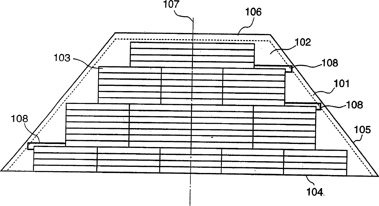
[0104] Fig. 1 is a graph showing that a covering material integrated solar cell module SR-02 (covering width W = 200mm, length λ = 2,000mm) available from Canon for a stepped roof is set on a trapezoidal roof. Sets the view of the state within scope 102. The length L1 of the eaves 104 of this roof is 12,000 mm, the length L2 of the ridge 106 is 5,000 mm, and the slope length A1 of the roof is 4,500 mm. Follow the steps shown in the flowchart of FIG. The interval g1 of the range 102 is 0 mm, the interval g2 from the roof ridge 106 to the allowable installation range 102 is 200 mm, and the interval g3 from the roof boundary 105 to the allowable installation range 102 is 200 mm. The setup steps are briefly described below. In the flow chart of FIG. 20, the same numerals as those in FIG. 19 denote the same steps, and their detailed descriptions will be omitted.

[0105] [Calculation of maximum number of set rows (steps S1 to S3)]

[0106] In the present embodiment, the covering...

no. 2 example

[0122] FIG. 7 is a view showing a state in which the above-described covering material-integrated solar cell module SR-02 is installed in the allowable installation range 102 of the roof installation surface 101 similarly to FIG. 1 . Following the steps shown in the flowchart of FIG. 21 , let the offset width 609 be 200mm. The setup steps are briefly described below. In the flowchart of FIG. 21, the same numerals as those in FIG. 19 denote the same steps, and their detailed descriptions will be omitted. Calculate the maximum setting number Cmax (steps S1 to S3), calculate the maximum setting number Nmax (step S4) of each row and the setting (step S5) at the central part of the setting surface is the same as the operation in the first embodiment, its Detailed description will be omitted.

[0123] [Offset (step S7)]

[0124] Since the offset width 609 is 200 mm, the module group is alternately offset to the left or right by 100 mm in row units.

[0125] [judgment (step S8)] ...

no. 3 example

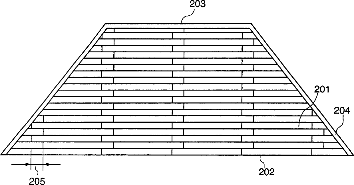
[0135] FIG. 12 is a view showing a state where the above-described covering material-integrated solar cell module SR-02 is installed in an allowable installation range 1202 of a triangular roof. The length L1 of the eaves 1204 of this roof is 9,200 mm, and the slope length A1 of the roof is 5,050 mm. Follow the steps shown in the flow chart of FIG. The distance g3 from the roof boundary 1205 to the allowable installation range 1202 is 200 mm. The setup steps are briefly described below. In the flowchart of FIG. 22, the same numerals as those in FIG. 19 denote the same steps, and their detailed descriptions will be omitted.

[0136] [Calculation of maximum number of set rows (steps S1 to S3)]

[0137] The length A of the allowable setting range 1202 in the oblique direction is given by:

[0138] A=A1-g1=5,050-200=4,850mm

[0139] The number of rows C is given by the following inequality, and the maximum set number of rows Cmax is 24:

[0140] C≤4,850 / 200=24.25

[0141] [c...


PUM


Abstract

To optimally arrange roofing material integrated solar battery modules having a rectangular form and same size on a roof setting surface, an arrangement range in which the solar battery modules can be arranged on the roof setting surface is determined. An arranging direction of the solar battery modules is determined. The number of solar battery modules which can be arranged almost horizontally in a line in the determined arranging direction and within the arrangement range is calculated. Solar battery modules of a line in a number not more than the calculated number are combined to form a solar battery module group. The solar battery module groups are arranged to set a center of the solar battery module group within the determined arrangement range and near a line almost vertically dividing the surface into two parts. The above operations are repeated a number of times corresponding to the number of lines of solar battery module groups which can be vertically arranged in the determined arranging direction and within the arrangement range.

Description

technical field [0001] The present invention relates to a method of arranging solar cell modules and a solar cell module array, and in particular to a method of arranging solar cell modules having a rectangular shape and the same size on an installation surface such as a roof, and a solar cell module array installed by the arranging method . Background technique [0002] As a method of arranging covering materials on the roof surface, especially stepping roof or Bermuda-type roofing materials, the method of two lap joints (Fig. 2) or the Mechigai covering method / offset covering method ( image 3). The advantage of these covering material configuration methods is that a good appearance can be obtained, because the covering material 201 is offset with a predetermined joint from the eaves (eaves) 202 as the bottommost edge of the roof to the ridge (ridge) 203 as the topmost edge of the roof. Shift width 205 configuration. In these disposition methods, for weathering, the join...

Claims


Application Information

Patent Timeline
Patent Type & Authority Patents(China)
IPC IPC(8): E04D1/00E04D1/30E04D3/40E04D13/18F24J2/04F24J2/52H01L31/042H01L31/048
CPCY02B10/20Y10S126/906F24J2/045F24J2/5211H01L31/0482Y02E10/50Y10S136/291Y02B10/12H01L31/048Y02E10/47H02S20/23F24S20/67F24S25/20F24S2201/00Y02B10/10E04D13/00
Inventor 牧田英久深江公俊高林明治盐见哲糸山诚纪
Owner CANON KK
Why Eureka
Try Eureka