Nuclear reactor cooling equipment and its operation method

A technology for cooling equipment and reactors, used in reactors, reactor fuel elements, nuclear power plant auxiliary equipment, etc., can solve the problem of increasing radiation dose, and achieve the effects of reducing radiation dose, increasing decay heat radiation, and eliminating decay heat radiation.

Inactive Publication Date: 2004-11-03
KK TOSHIBA
View PDF0 Cites 0 Cited by
  • Summary
  • Abstract
  • Description
  • Claims
  • Application Information

AI Technical Summary

Problems solved by technology

[0018] However, the reactor water flowing out from the reactor pressure vessel 1 contains radioactive dirt, and the dirt accumulates at the bottom of the reactor well

Method used


Image

  • Nuclear reactor cooling equipment and its operation method
  • Nuclear reactor cooling equipment and its operation method
  • Nuclear reactor cooling equipment and its operation method

Examples


Embodiment Construction

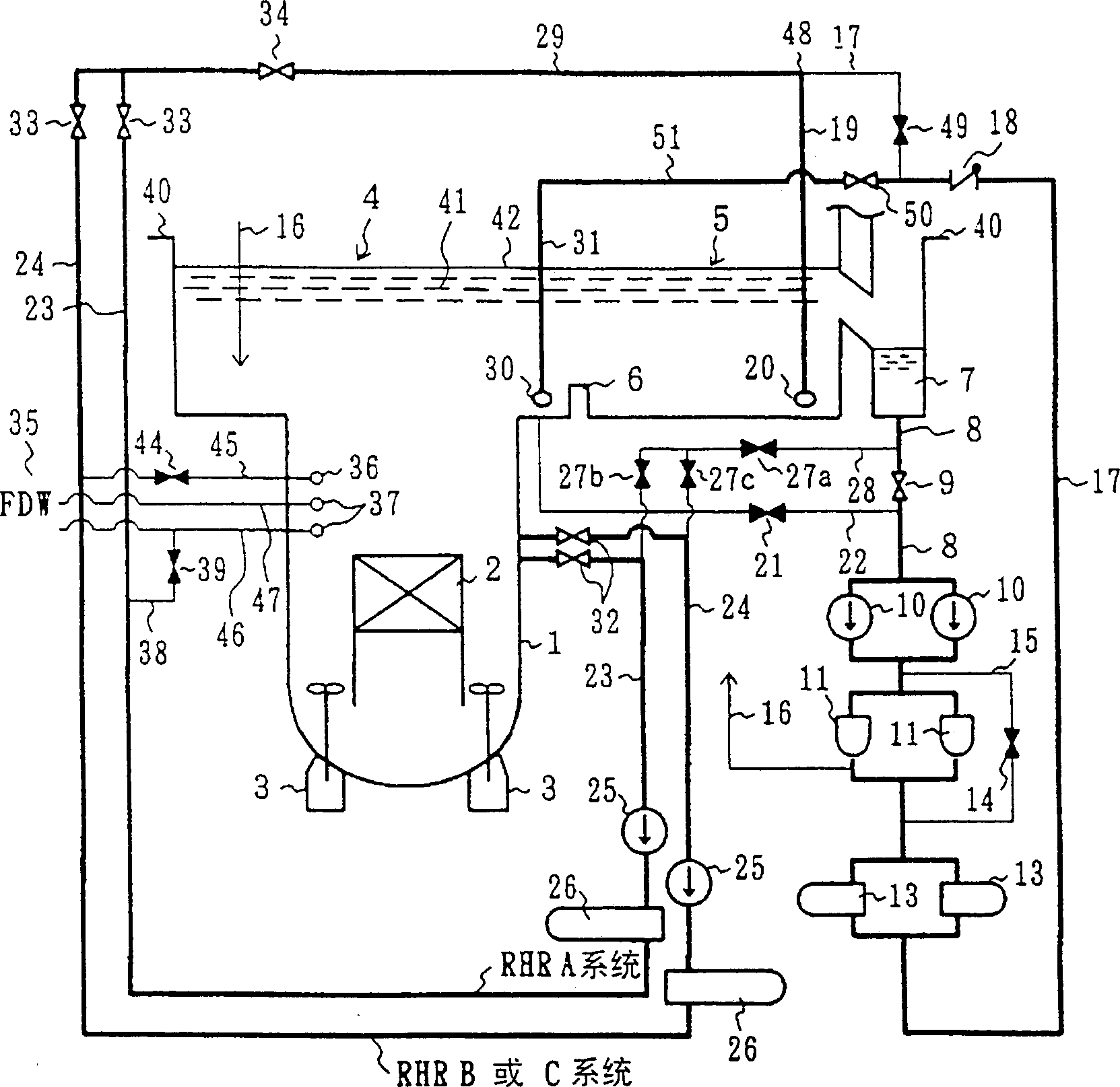
[0087] use figure 1 , the first embodiment of the reactor cooling equipment of the present invention will be described in detail.

[0088] exist figure 1 in, for and Figure 16 The same parts are marked with the same symbols, and the description of the repeated parts is omitted. The difference between this embodiment and the previous example is that the part connecting the downstream side of the fuel pool return line 17 and the downstream side of the RHR-FPC connection line 29 is set as a confluence point 48, and at this confluence point 48 The branch is connected to the FPC return water injection pipeline 19. And, a closing valve 49 is set on the fuel pool return line 17, and then branched from the outlet side of the check valve 18 of the fuel pool return line 17, and the FPC return flow line 51 is connected through the closing valve 50. The flow line 51 is connected to the RHR return water injection line 31 .

[0089] That is to say, the pipeline system of this embodim...


PUM


Abstract

The invention discloses a nuclear reactor cooling equipment and its operation method. To reduce radiation exposure dose of workers during acces to a reactor pressure vessel in reactor well and remove decay heat without disturbing replacing work of fuel assemblies and control rods. In a reactor well and a fuel pool constructed in a reactor building, the outlet side of the fuel pool return line of a fuel pool cooling and purifying system line placed downstream the skimer surge line neighboring to the fuel pool is placed in the reactor well and the outlet side of reactor residual heat removal system lines are placed in the fuel pool. By this, radioactive crad contained in reactor water in the reactor pressure vessel is prevented from accumulating on the bottom of the reactor well and so radioactive exposure dose of workers can be reduced.

Description

technical field [0001] The invention relates to a reactor cooling device and its operation method which can reduce the radiation dose of the reactor well and eliminate the decay heat radiation without affecting the workability when it is close to the reactor pressure vessel in the nuclear power plant. Background technique [0002] refer to Figure 16 , illustrating the reactor cooling equipment of the improved boiling type nuclear power plant. [0003] Figure 16 Represents an overview of piping systems for reactor cooling equipment of the past. exist Figure 16 In , symbol 1 is the reactor pressure vessel, indicating the state where the reactor cover is removed, and the shroud head, steam-water separator and steam dryer on the core 2 are removed. Symbol 3 represents the overview of the internal pump (internal pump), Figure 16 The thick lines in the figure indicate the water flow state such as cooling water, stack water, pool water, etc.; the thin lines indicate the non-fl...

Claims


Application Information

Patent Timeline
IPC IPC(8): G21C15/18G21C19/02G21C19/07G21C19/30G21C19/307G21D1/00G21D1/02
CPCY02E30/40Y02E30/00Y02E30/30
Inventor 石桥文彦近藤隆久黑田理知高山拓治小林实山本雄司
Owner KK TOSHIBA
Why Eureka
Try Eureka