Energy-saving oxygenation system in sewage treatment
An aeration device and sewage treatment technology, which is applied in water/sewage treatment, biological water/sewage treatment, water/sludge/sewage treatment, etc., can solve the problems of high energy consumption and low efficiency, and achieve low energy consumption and high solubility Increase and decrease the effect of high energy consumption phenomenon
- Summary
- Abstract
- Description
- Claims
- Application Information
AI Technical Summary
Problems solved by technology
Method used
Image
Examples
specific Embodiment approach 1
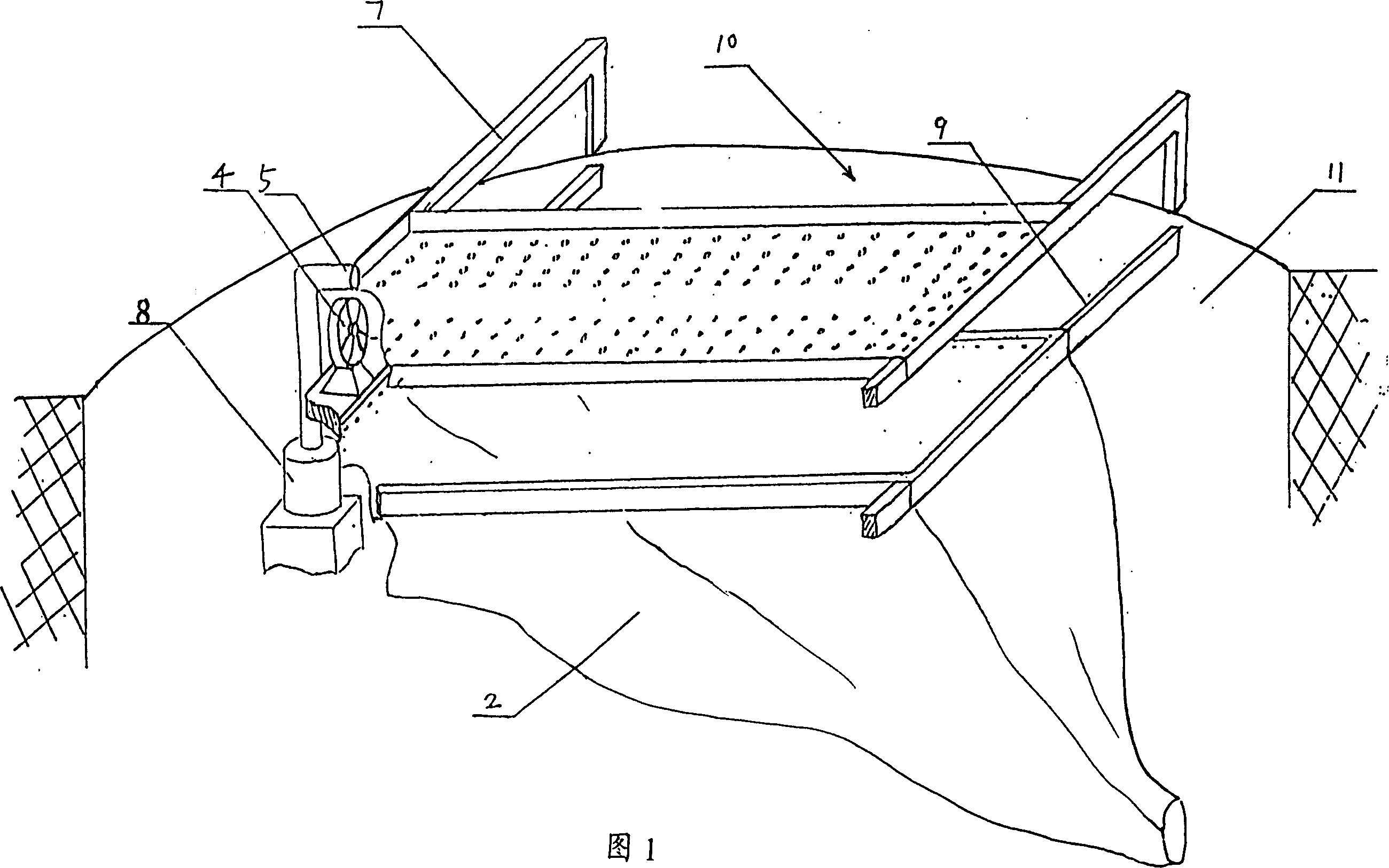
[0023] The energy-saving aeration device for sewage treatment as shown in Figure 1, in the sewage pool 10, the shower pool 1 is fixed above the water surface by the support rod 7, and the funnel-shaped directional water tank 2 is set on the water surface below the shower pool, and the water tank 2 is directional. The water tank is fixed on the sewage tank wall 11 by the support rod 9, and the upper opening of the directional drain tank is higher than the water surface. A plurality of shower holes are arranged on the bottom surface of the shower pool 1, and the shower holes are arranged in a U shape on the bottom surface of the shower pool 1, and the outlet pipe 5 of the low-lift, high-flow submersible pump 8 arranged in the sewage is connected with the U-shaped array shower. The opening ends of the water holes are connected, and the axial flow fan 4 is arranged between the shower pool 1 and the directional drain tank 2, and the axial flow fan 4 corresponds to the opening ends o...
specific Embodiment approach 2
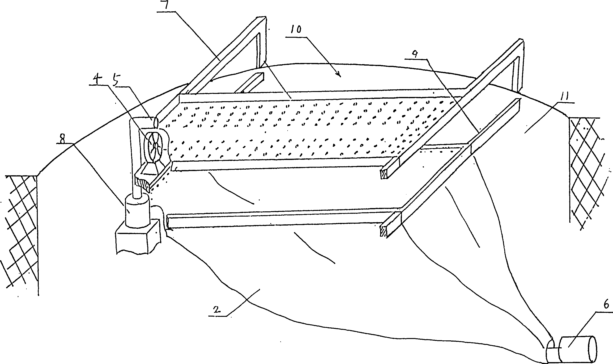
[0025] Such as figure 2 In the shown energy-saving aeration device for sewage treatment, the shower tank 1 is fixed above the water surface through the support rod 7 in the sewage tank 10, and the directional discharge tank 2 is set on the water surface below the shower tank, and the directional discharge tank passes through the support rod 9 Fixed on the sewage pool wall 11, the upper opening of the directional diarrhoea is higher than the water surface. A plurality of shower holes are arranged on the bottom surface of the shower pool 1, and the shower holes are arranged in a U shape on the bottom surface of the shower pool 1, and the outlet pipe 5 of the low-lift, high-flow submersible pump 8 arranged in the sewage is connected with the U-shaped array shower. The opening ends of the water holes are connected, and the axial flow fan 4 is arranged between the water shower tank 1 and the directional drain tank 2, and the axial flow fan 4 is corresponding to the opening ends of ...
specific Embodiment approach 3
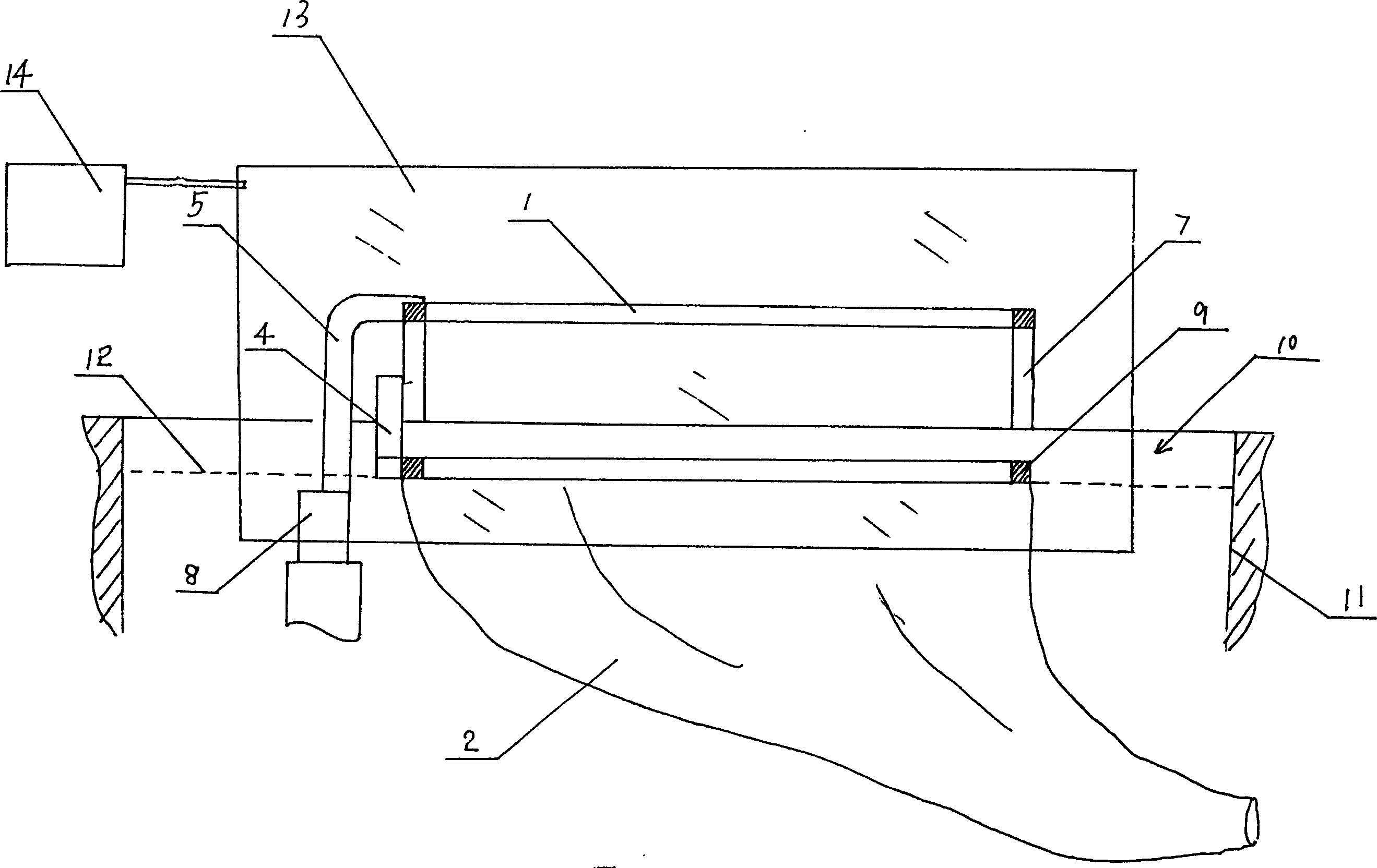
[0027] Such as image 3 In the shown energy-saving aeration device for sewage treatment, the shower tank 1 is fixed above the water surface through the support rod 7 in the sewage tank 10, and a funnel-shaped directional water tank 2 is set on the water surface below the shower tank, and the directional water tank is supported by Rod 9 is fixed on the sewage pool wall 11, and the upper opening of the directional diarrhoea is higher than the water surface 12. A plurality of shower holes are arranged on the bottom surface of the shower pool 1, and the shower holes are arranged in a U shape on the bottom surface of the shower pool 1, and the outlet pipe 5 of the low-lift, high-flow submersible pump 8 arranged in the sewage is connected with the U-shaped array shower. The opening ends of the water holes are connected, and the axial flow fan 4 is arranged between the water shower tank 1 and the directional drain tank 2, and the axial flow fan 4 is corresponding to the opening ends ...
PUM
 Abstract
Description
Claims
Application Information
 - R&D
- Intellectual Property
- Life Sciences
- Materials
- Tech Scout
- Unparalleled Data Quality
- Higher Quality Content
- 60% Fewer Hallucinations
Browse by: Latest US Patents, China's latest patents, Technical Efficacy Thesaurus, Application Domain, Technology Topic, Popular Technical Reports.
© 2025 PatSnap. All rights reserved.Legal|Privacy policy|Modern Slavery Act Transparency Statement|Sitemap|About US| Contact US: help@patsnap.com


