Power generating installation comprising a driving engine and a generator

A technology for generating sets and generators, which is applied in the direction of electromechanical devices, electric components, synchronous motors with stationary armatures and rotating magnets, etc., which can solve problems such as engine cooling without explanation, achieve simple fixing or supporting methods, and reduce costs , cost saving effect

Inactive Publication Date: 2005-02-02
MOTORENFABRIK HATZ GMBH & CO KG
View PDF2 Cites 0 Cited by
  • Summary
  • Abstract
  • Description
  • Claims
  • Application Information

AI Technical Summary

Problems solved by technology

The document does not addre

Method used


Image

  • Power generating installation comprising a driving engine and a generator
  • Power generating installation comprising a driving engine and a generator
  • Power generating installation comprising a driving engine and a generator

Examples


Embodiment Construction

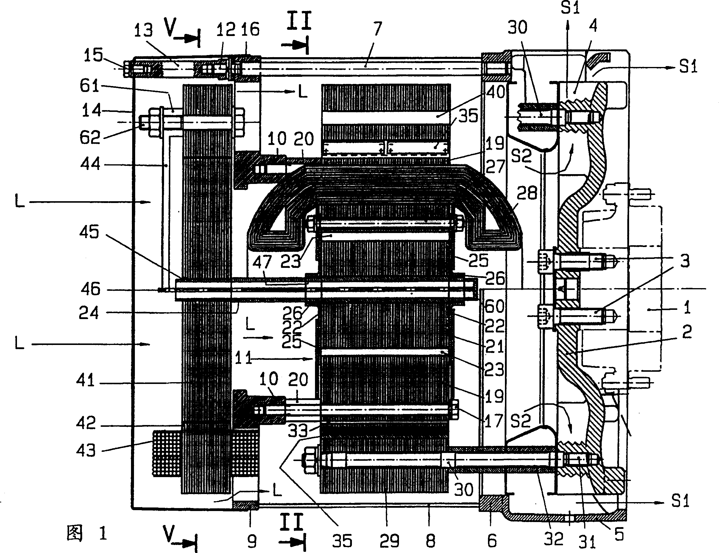
[0027] The electrical equipment constituting the generator shown in FIGS. 1 to 3 relates to a unit consisting of a drive motor and a synchronous generator. A diesel engine is preferably considered as the drive engine, for which only the end of the crankshaft 1 connected to the synchronous generator is shown in dotted lines in the figure. The fan impeller 2 is connected with the bolt 3 at the end of the crankshaft 1 . The fan wheel 2 has a set of blades for generating a motor-cooling airflow as indicated by the arrow S1 , wherein the air flowing according to the arrow S2 corresponds to the cold air flowing out of the generator housing 8 after cooling the generator. As shown in FIG. 1 , the generator housing end cover 9 on the power output side has intake openings for the flow of cooling air according to arrow L. As shown in FIG. In order for this cooling air flow to achieve its sufficient cooling effect within the generator housing 8 , the protective cover 14 has one or more (...


PUM


Abstract

In a power generator unit composed of a drive motor and a generator, particularly a diesel engine and a synchronous generator with a stationary rotor winding (28) and permanent magnets (35) arranged in the rotor (29), for excitation of the generator, its rotor (29) forms the flywheel of the diesel engine, as an external rotor, and its stator (11), arranged within the rotor, carries the rotor winding (28).

Description

technical field [0001] The invention relates to a generator set composed of a driving engine and a generator, especially a diesel engine and a synchronous generator, which includes a fixed armature winding and a permanent magnet installed in the rotor for generator excitation, wherein the design is The generator rotor of the outer rotor constitutes the flywheel of the diesel engine, and the stator of the generator has armature windings and is located inside the rotor. Background technique [0002] In German open document 3009279 a kind of generator that can be driven by the automobile transmission system is introduced, wherein the generator is designed as a heteropolar generator, its rotor is fixed on the flywheel of the drive system, and, for the excitation of the generator, in its Permanent magnets are arranged on the rotor. Here, the voltage is generated in the stator windings, which are fastened to the drive system housing around the rotor. In this drive system, which ...

Claims


Application Information

Patent Timeline
IPC IPC(8): H02K1/18H02K1/27H02K1/28H02K5/04H02K7/18H02K15/03H02K21/00H02K21/22
CPCH02K7/1807H02K21/222H02K7/1815H02K21/22H02K21/00
Inventor 厄恩斯特·哈兹弗朗兹·莫泽
Owner MOTORENFABRIK HATZ GMBH & CO KG
Why Eureka
Try Eureka