Polarizer based on guided wave resonance
A guided wave resonance and polarizer technology, applied in the field of polarizers and polarizers with high polarization extinction ratio, can solve problems such as performance differences, limit the application range of devices, and reduce device performance, and achieve low light intensity loss and small insertion loss. , the effect of reducing insertion loss
- Summary
- Abstract
- Description
- Claims
- Application Information
AI Technical Summary
Problems solved by technology
Method used
Image
Examples
Embodiment 1
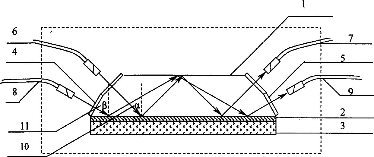
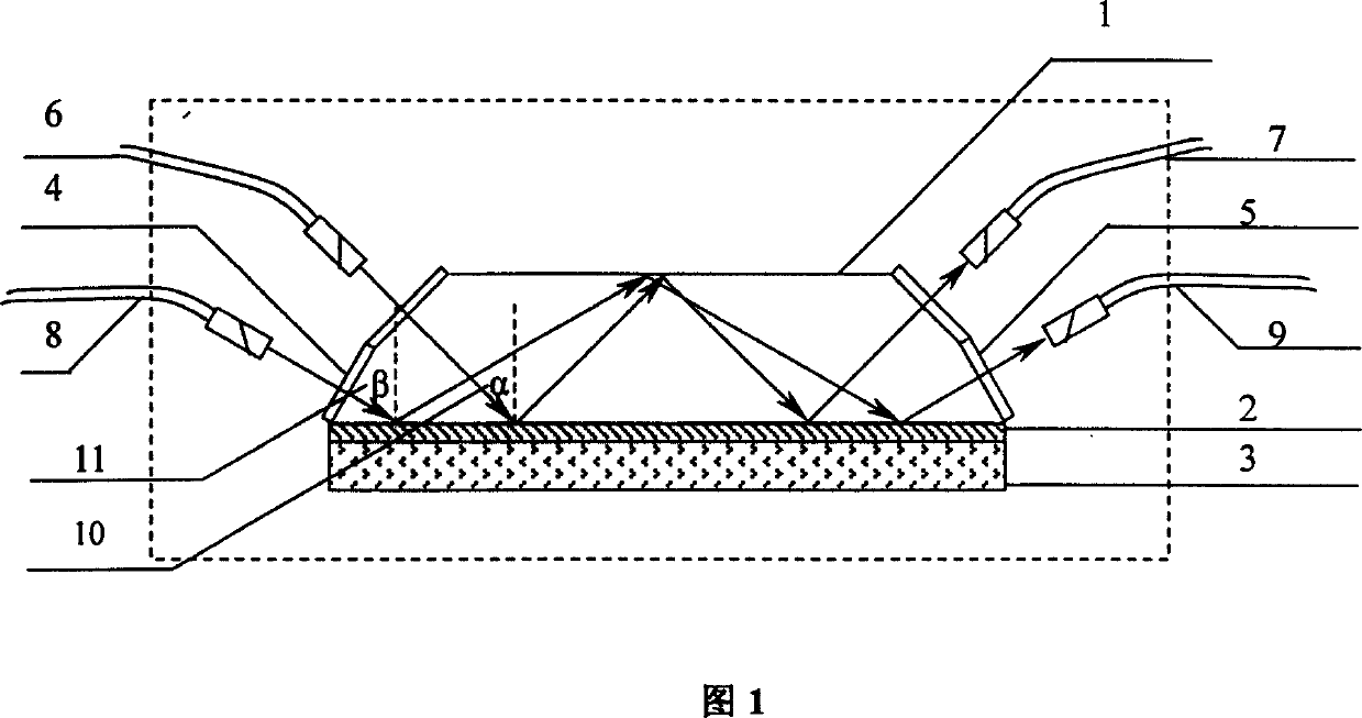
[0026] The polarizer of the present invention is composed of an elongated prism 1, a bottom metal film 2, a dielectric film 3, and an antireflection film 4, 5, the elongated prism 1, the bottom metal film 2, and the dielectric film 3 are arranged from top to bottom, and the antireflection film 4, 5 Plated on both sides of the elongated prism 1, the metal film 2 on the bottom and the dielectric film 3 form a single-sided metal clad waveguide structure, the dielectric film 3 is the wave guiding layer, and the metal film 2 on the bottom is the cladding layer. The first and second lead-in fiber joints (6, 8) and the first and second lead-out fiber joints (7, 9) lead the laser beam into or out of the polarizer, wherein the first lead-in fiber joint (6), the first lead-out The optical fiber connector (7) is symmetrical with respect to the elongated prism 1, and the second leading-in optical fiber connector (8) and the second deriving optical fiber connector (9) are symmetrical with r...
Embodiment 2
[0031] The polarizer of the present invention is composed of an elongated prism 1, a bottom metal film 2, a dielectric film 3, and an antireflection film 4, 5, the elongated prism 1, the bottom metal film 2, and the dielectric film 3 are arranged from top to bottom, and the antireflection film 4, 5 Plated on both sides of the elongated prism 1, the metal film 2 on the bottom and the dielectric film 3 form a single-sided metal clad waveguide structure, the dielectric film 3 is the wave guiding layer, and the metal film 2 on the bottom is the cladding layer. The first and second lead-in fiber joints (6, 8) and the first and second lead-out fiber joints (7, 9) lead the laser beam into or out of the polarizer, wherein the first lead-in fiber joint (6), the first lead-out The optical fiber connector (7) is symmetrical with respect to the elongated prism 1, and the second leading-in optical fiber connector (8) and the second outgoing optical fiber connector (9) are symmetrical with r...
Embodiment 3
[0036] The polarizer of the present invention is composed of an elongated prism 1, a bottom metal film 2, a dielectric film 3, and an antireflection film 4, 5, the elongated prism 1, the bottom metal film 2, and the dielectric film 3 are arranged from top to bottom, and the antireflection film 4, 5 Plated on both sides of the elongated prism 1, the metal film 2 on the bottom and the dielectric film 3 form a single-sided metal clad waveguide structure, the dielectric film 3 is the wave guiding layer, and the metal film 2 on the bottom is the cladding layer. The first and second lead-in fiber joints (6, 8) and the first and second lead-out fiber joints (7, 9) lead the laser beam into or out of the polarizer, wherein the first lead-in fiber joint (6), the first lead-out The optical fiber connector (7) is symmetrical with respect to the elongated prism 1, and the second leading-in optical fiber connector (8) and the second outgoing optical fiber connector (9) are symmetrical with r...
PUM
| Property | Measurement | Unit |
|---|---|---|
| thickness | aaaaa | aaaaa |
| thickness | aaaaa | aaaaa |
| length | aaaaa | aaaaa |
Abstract
Description
Claims
Application Information
 - R&D
- Intellectual Property
- Life Sciences
- Materials
- Tech Scout
- Unparalleled Data Quality
- Higher Quality Content
- 60% Fewer Hallucinations
Browse by: Latest US Patents, China's latest patents, Technical Efficacy Thesaurus, Application Domain, Technology Topic, Popular Technical Reports.
© 2025 PatSnap. All rights reserved.Legal|Privacy policy|Modern Slavery Act Transparency Statement|Sitemap|About US| Contact US: help@patsnap.com


