Intensified full-bridge phase-shift soft switch converter

A full-bridge phase-shifting and converter technology, which is applied in the direction of converting irreversible DC power input to AC power output, high-efficiency power electronic conversion, and climate sustainability. Unable to achieve zero-voltage turn-on and other problems, to achieve the effect of improving efficiency, reducing oscillation, and simplifying the circuit

Inactive Publication Date: 2005-03-16
EMERSON NETWORK POWER CO LTD
View PDF0 Cites 3 Cited by
  • Summary
  • Abstract
  • Description
  • Claims
  • Application Information

AI Technical Summary

Problems solved by technology

[0004] 1. The energy of the junction capacitance of the lagging arm is small, so it may not be able to achieve zero voltage turn-on at light load, so the light load loss is large
[0005] 2. The commutation process of the output rectifier tube causes voltage oscillation at both ends, increasing diode loss and voltage stress
[0006] In order to solve the above problems, at present, some use auxiliary network, such as figure 2 As shown, the principle is that when the switch tube Q3 or Q4 is turned on, the auxiliary capacitor and the inductor resonate. When the voltage across the capacitor is zero, the anti-parallel diode conducts, and the current in the auxiliary inductor remains approximately constant. When the switch tube Q3 or Q4 When it is turned off, the current in the resonant inductor and the current in the inductor L1 drain the energy of the junction capacitance of the switching tube Q3 and Q4 together, and the voltage oscillation during the commutation process of the output rectifier tube of this method still exists

Method used


Image

  • Intensified full-bridge phase-shift soft switch converter
  • Intensified full-bridge phase-shift soft switch converter
  • Intensified full-bridge phase-shift soft switch converter

Examples


Embodiment Construction

[0033] The following describes the present invention in further detail based on the drawings and embodiments:

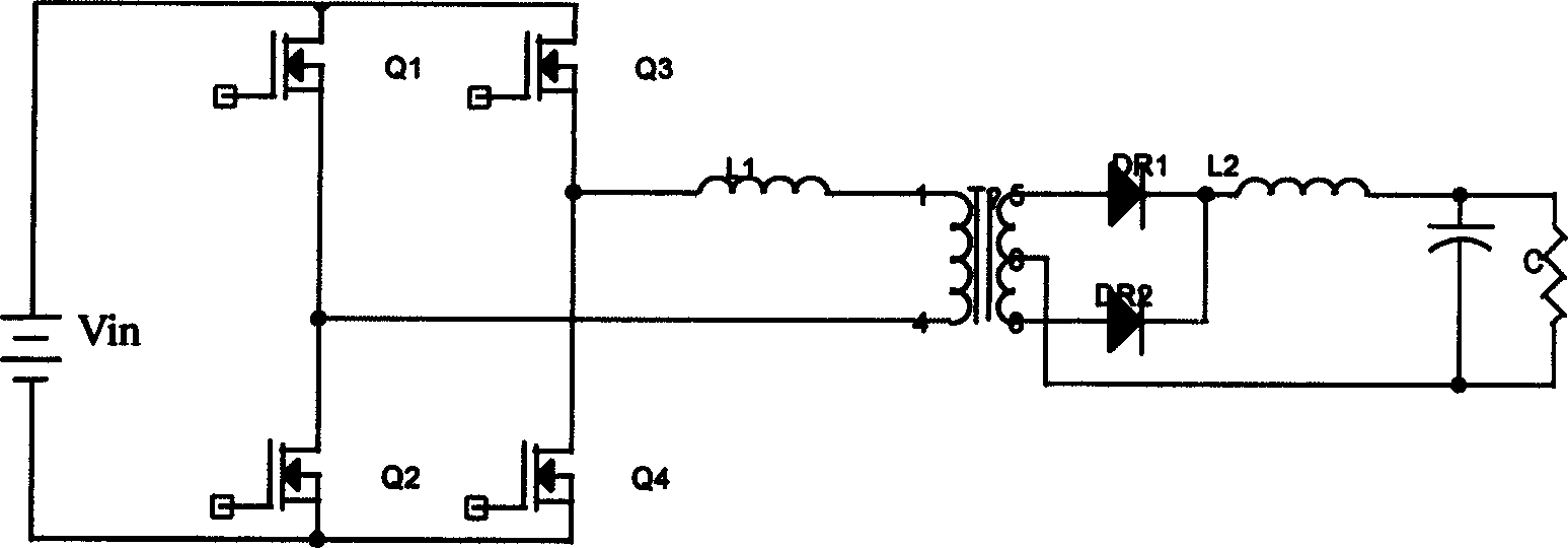
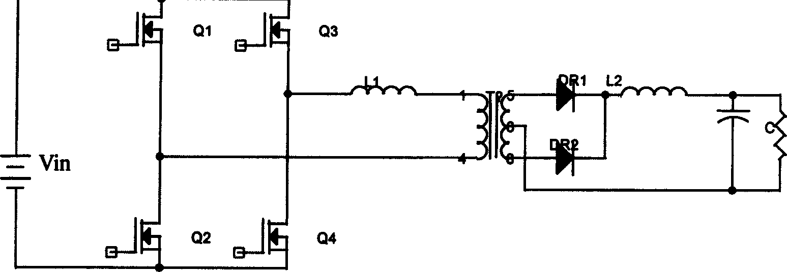
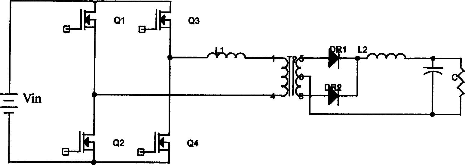
[0034] according to Figure 6 , The switch tubes Q1, Q2, Q3 and Q4 constitute a basic full-bridge phase-shifting circuit, which also includes an inductor L1 connected in series to the primary end of the transformer. The full-bridge phase-shifting circuit is connected to a voltage resonance network, which includes separate parallel Connected to the connection point M between the primary side of the transformer and the inductor L1 and the capacitor C1 and diode D1, as well as the capacitor C2 and the diode D2 across the input voltage, through the inductor L1 connected in series to the primary side of the transformer to form voltage resonance, this design can be realized The zero voltage turn-on under light load conditions, and the auxiliary capacitors C1, C2 and diodes D1, D2 during the commutation process can suppress the voltage oscillation of the output rectifiers DR1 a...


PUM


Abstract

This invention relates a reinforcement full bridge phase-shift soft-switch method and a converter used in power source or power system, including a full bridge phase-shift circuit made up from switch tubes and a primary side end inductor L1 serial-connected to the transformer. It is characterized by the said full bridge phase-shift circuit connecting to the voltage resonant network which enables delayed switch tubes to have the complete zero voltage when turned-on, and to suppress the peak voltage of output commutation diode. The voltage resonant network comprises connecting points parallel-connected to the transformer primaryside, inductory L1 connecting point, capacitor C1 at both ends of input voltage, diode D1 and capacitor C2 and diode D2 to form voltage resonance via inductor L1 serial-connected to the transformer primary side.

Description

【Technical Field】 [0001] The invention relates to a conversion device used in a power supply or similar power system, and more particularly to an enhanced full-bridge phase-shift soft switching converter. 【Background technique】 [0002] The full-bridge phase-shift soft switching technology can realize the zero-voltage turn-on of the switching tube, and has been widely used in high-power applications. Its basic topology is as figure 1 As shown, figure 1 The four switching tubes Q1, Q2, Q3 and Q4 are driven by a duty cycle close to 50%. The switching tubes Q1 and Q2 are driven complementarily, and the switching tubes Q3 and Q4 are driven complementarily; the driving of the switching tube Q4 is delayed relative to the switching tube Q1. In terms of angle, assuming that the initial state is that the switching tube Q1 and Q4 are turned on, the energy is transferred from the primary side to the secondary side. It is assumed that the output rectifier tube DR1 is turned on. If the swit...

Claims


Application Information

Patent Timeline
Patent Type & Authority Patents(China)
IPC IPC(8): H02M7/48
CPCY02B70/1491Y02B70/10
Inventor 阮世良吴建华陈利强
Owner EMERSON NETWORK POWER CO LTD
Why Eureka
Try Eureka