
Mixer systems

A kind of technology of equipment, catheter, applied in the field of mixing equipment

Inactive Publication Date: 2005-04-06
PENN STATE RES FOUND
View PDF4 Cites 1 Cited by
  • Summary
  • Abstract
  • Description
  • Claims
  • Application Information

AI Technical Summary

Problems solved by technology

However, in many non-Newtonian shear-thinning liquids, especially under the severe circulation and mixing conditions present in fermentation processes, these techniques cannot ensure proper circulation and mixing at sufficient rates necessary to facilitate these reaction processes. mix

Method used


Image

  • Mixer systems
  • Mixer systems
  • Mixer systems

Examples


example 1

[0085] Conduit diameter 18″

[0086] Groove diameter 36″

[0087] Liquid level 72″

[0088] Tank height 84″

[0089] Input power 23.6HP / kgal

[0090] Jet rate 0.5vvm

[0091] up through the conduit and through

[0092] Downward liquid flow rate in the annular area 3 / 2 liters / second

[0093] The turnover time of the liquid in the whole tank is 3.9 seconds

[0094] Liquid phase throughout the tank volume

[0095] Species transfer coefficient (K L a) 18.9 seconds -1

example 2

[0097] Conduit diameter 24″

[0098] Groove diameter 36″

[0099] Liquid level 72″

[0100] Tank height 84″

[0101] Input power 23.6HP / kgal

[0102] Jet rate 0.5vvm

[0103] up through the conduit and through

[0104] Downward liquid flow rate in the annular area 5 / 6 liters / second

[0105] The turnover time of the liquid in the whole tank is 2.3 seconds

[0106] Liquid phase throughout the tank volume

[0107] Species transfer coefficient (K L a) 16.5hr -1

example 3

[0109] Conduit diameter 18″

[0110] Groove diameter 36″

[0111] Liquid level 72″

[0112] Tank height 84″

[0113] Input power 23.6HP / kgal

[0114] Jet rate 0.1vvm

[0115] up through the conduit and through

[0116] Downward liquid flow rate in the annular area 444 l / s

[0117] The turnover time of the liquid in the whole tank is 2.7 seconds

[0118] Liquid phase throughout the tank volume

[0119] Species transfer coefficient (K L a) 10.3 hours -1


PUM


Abstract

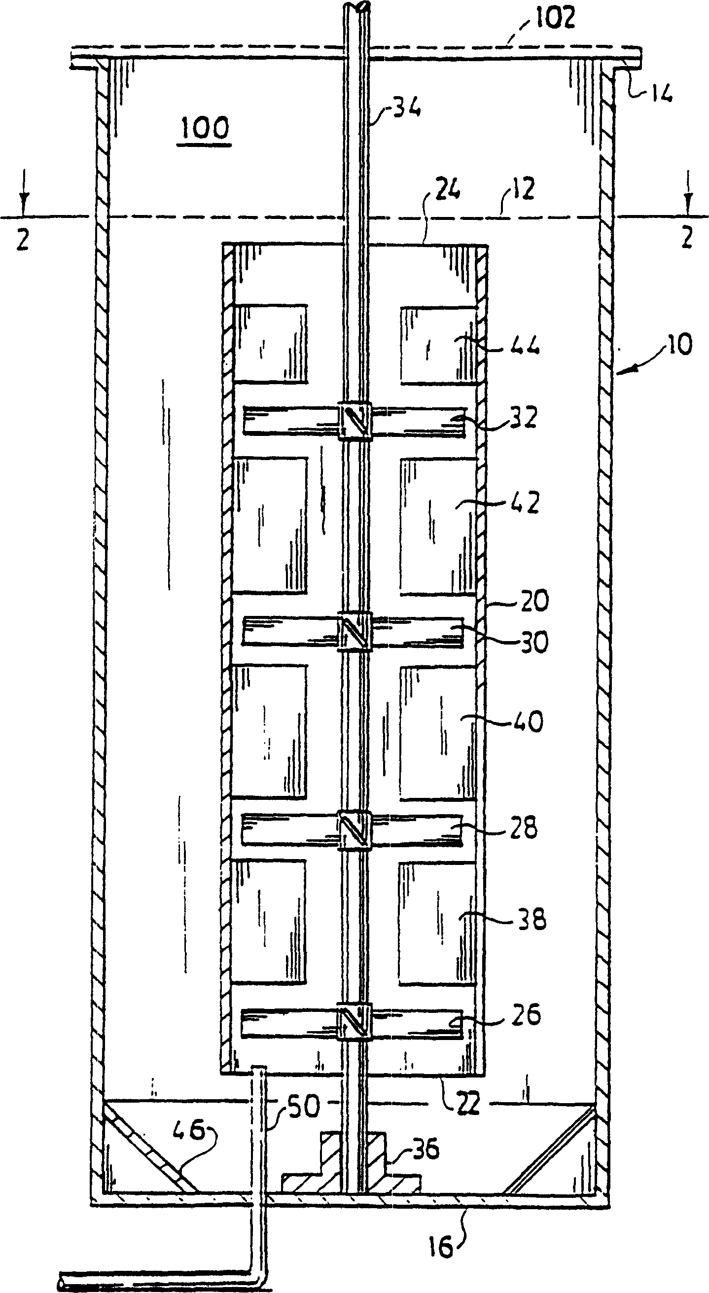
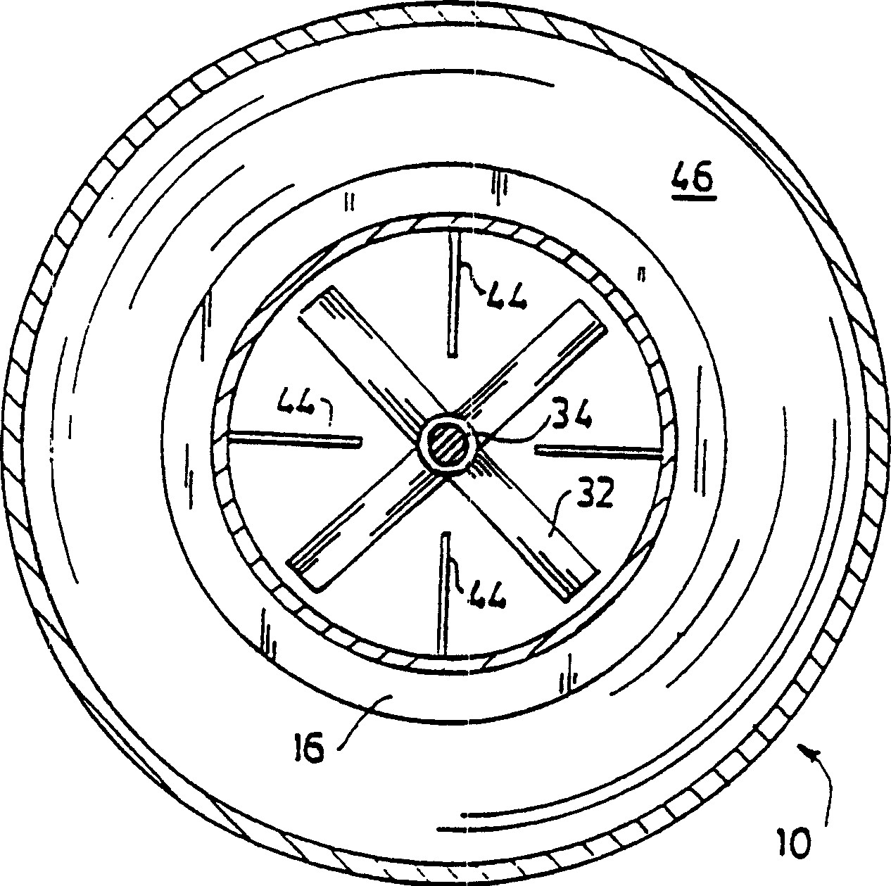
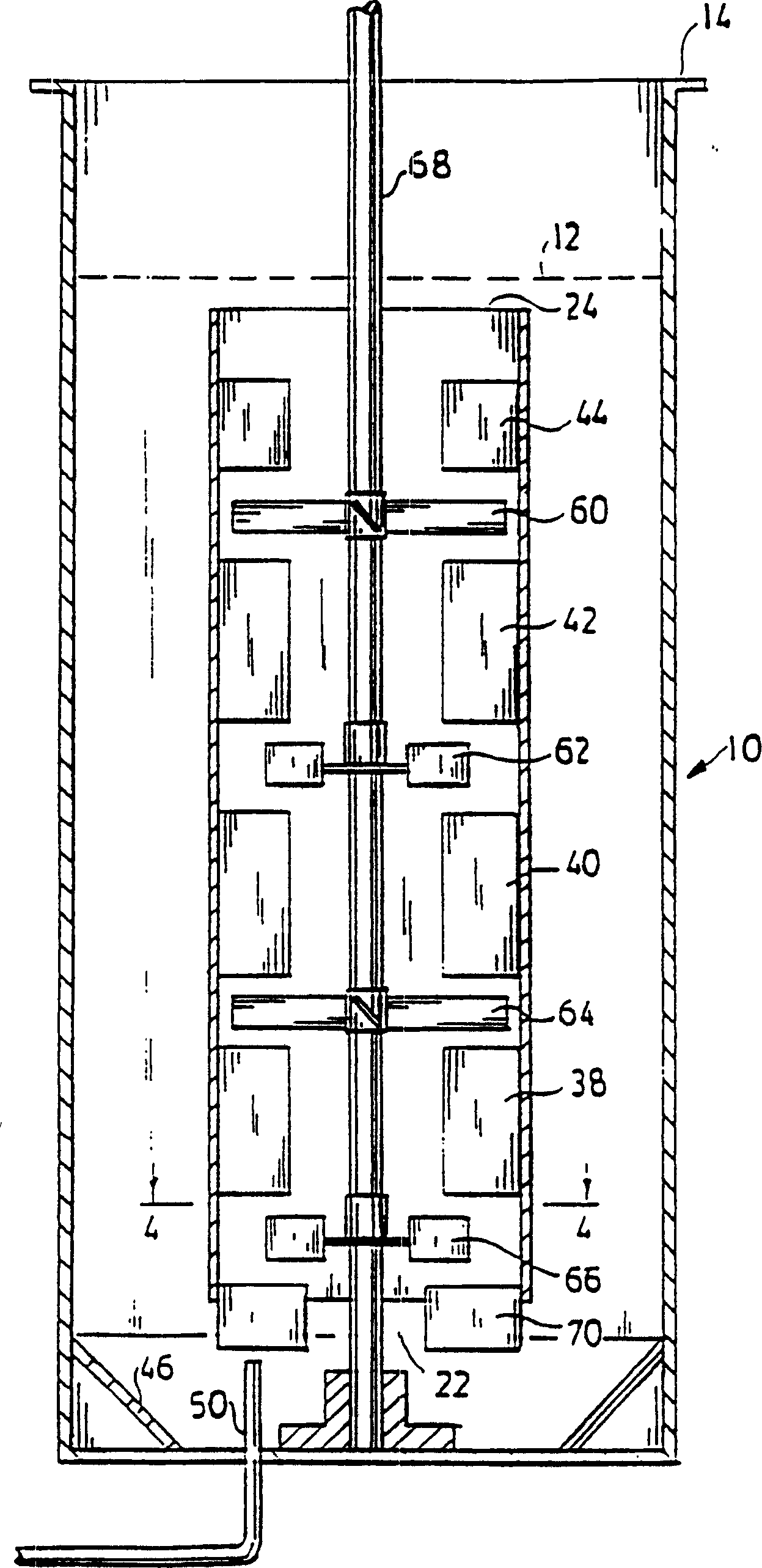
A system for providing improved bulk liquid mixing and effective gas-liquid contacting for mass transfer of the gas to the liquid, especially a non-Newtonian liquid, the viscosity of which decreases when under shearing conditions (shear thinning), in an upright tank. A process, such as fermentation which produces commercial quantities of polysaccharides such as xanthan gum, may be carried out in the tank. An upright draft tube is mounted within the tank and has a lower end spaced from the tank bottom and an upper end spaced below the surface of the liquid in the tank. A plurality of mixing impellers in the draft tube are sufficiently close to each other to establish a field or pattern of agitation to cause shear thinning and upflow throughout the draft tube and which may produce turbulence at the liquid surface. A plurality of radially inwardly projecting circumferentially spaced baffles extend from the draft tube and are proximate the mixing impellers to prevent swirling of the liquid within the draft tube. Gas may be sparged into the vessel in or adjacent to the lower end of the draft tube. A circulating co-current flow of gas and liquid, with intimate gas-liquid contact, is induced up through the draft tube and out the upper end of the draft tube so as to provide a high rate of mass transfer from the gas to the liquid. The flow including entrained gas turns down through the annular region between the tank wall and the draft tube for recirculation of the liquid and gas above the surface of the liquid, resulting in high gas holdup and gas-liquid contact in the downflow annular region and in the upflow draft tube region, without gas flooding of the impellers. The concentration of dissolved gas and the effectiveness of the system for gas-phase mass transfer is determined by reaeration of a test sample of the liquid.

Description

technical field [0001] This invention relates to mixing apparatus and, more particularly, to apparatus for circulating a liquid in a tank and effecting gas-liquid contact, especially when the liquid is non-Newtonian and has shear-thinning viscosity characteristics. Good liquid circulation and mixing and intimate gas-liquid contact facilitate the transfer of gas components to substances within the liquid. Background technique [0002] The invention is particularly applicable to biological reaction processes such as fermentation by circulating a slurry containing microorganisms and growth medium, especially when the fermentation process increases the viscosity of the slurry. The invention can improve the oxygenation condition and mixing effect of this kind of liquid, and promote the fermentation process. One type of fermentation process for which the present invention is particularly applicable is that used for the production of polysaccharides such as xanthan gum, and improv...

Claims


Application Information

Patent Timeline
Patent Type & Authority Patents(China)
IPC IPC(8): B01F27/91B01J19/18C12M1/06C12M1/08
CPCC12M27/02B01F2215/0463B01F2215/0431B01F7/00141C12M27/20B01F7/00633B01F7/00641C12M27/08B01F2003/04645C12M29/08B01J19/1875B01F3/04773B01F2003/04673B01F2215/045B01F2215/0422B01J2219/00768B01F7/00291B01F7/00116B01F7/00133B01F3/04609B01F23/23341B01F23/23353B01F23/23362B01F23/23421B01F27/0721B01F27/0723B01F27/0724B01F27/1125B01F27/192B01F27/191
Inventor 约翰·麦克沃特布拉德利·多米尼克普拉卡什·巴兰
Owner PENN STATE RES FOUND
Learn More