Optical record medium, optical information processing apparatus, and optical recording/reproducing method
一种光记录媒体、记录层的技术,应用在光学记录/再现/擦除方法、用光学方法记录/重现、光学记录载体等方向,能够解决光量不足等问题
- Summary
- Abstract
- Description
- Claims
- Application Information
AI Technical Summary
Problems solved by technology
Method used
Image


Examples
Embodiment 1
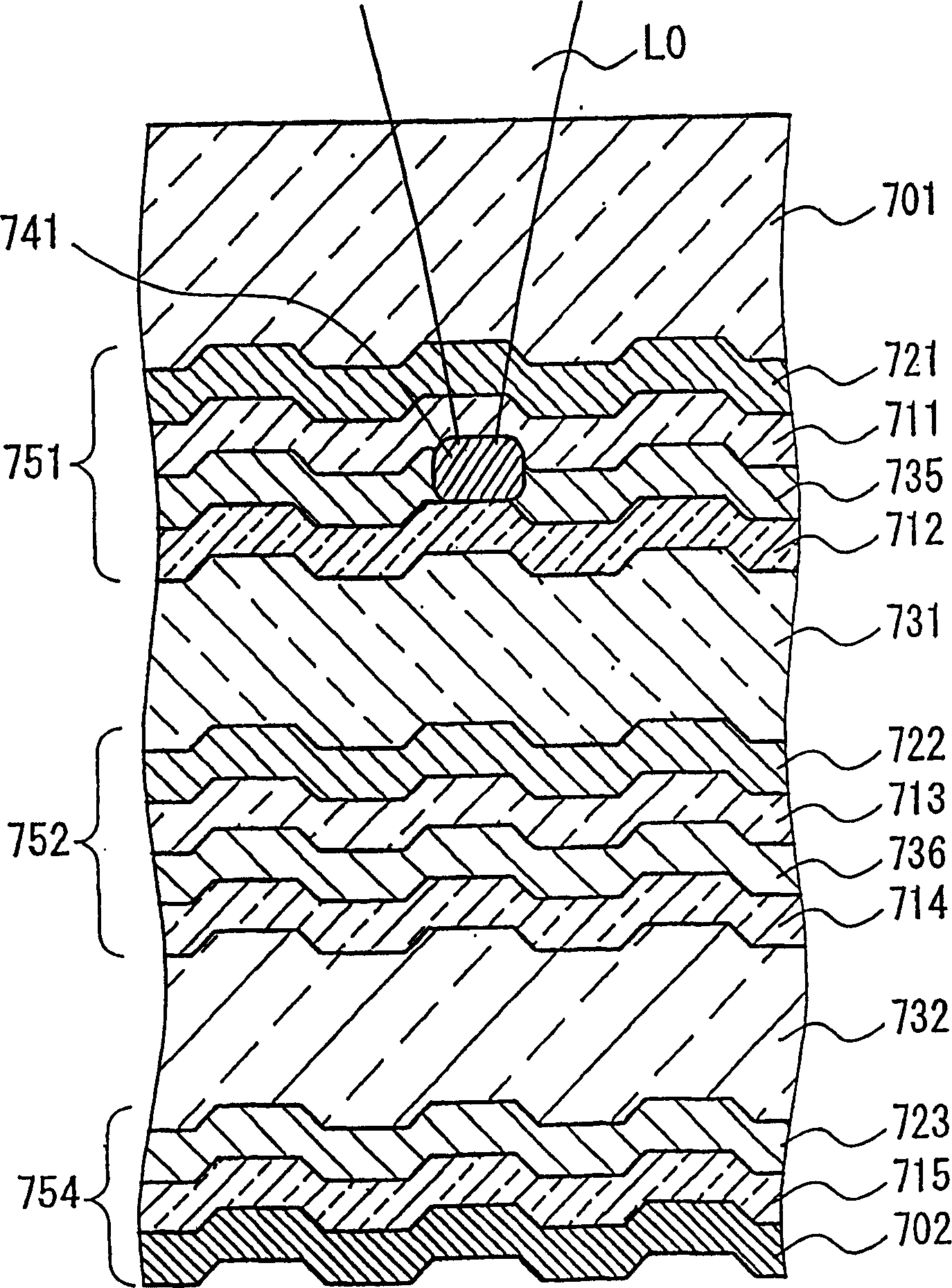
[0031] figure 1 The cross-sectional structure of the optical recording medium of Example 1 is shown. This optical recording medium is a multilayer optical recording medium in which a first recording layer 751, a second recording layer 752, and a final recording layer 754 are sequentially provided on a substrate 701 from the light (L0) incident side. Separation films 731 and 732 are provided between the respective recording layers.
[0032] The first recording layer 751 and the second recording layer 752 are layers of the same structure, and have recording films 721, 722, dielectric films 711, 713, and a reflection control film (corresponding to a variable reflection film) arranged in this order from the light (L0) incident side. 735, 736 and the structure of the dielectric film 712, 714.
[0033]The final recording layer 754 composed of the recording film 723 , the dielectric film 715 , and the reflective film 702 is arranged, and the second recording layer 752 and the sepa...
Embodiment 2
[0045] The optical recording medium of embodiment 2 is the recording layers 751, 752 other than the final recording layer 754 of the optical recording medium of embodiment 1 and Figure 6 A structure obtained by replacing the structure shown. in addition, Figure 6 The case of reading and writing on the first recording layer 751 is shown in .
[0046] Figure 6 Among them, 711 and 712 represent dielectric films, and 735 represents a reflection control film, which is the same as that of Embodiment 1. The recording film 721 is substantially transparent to the light L0 and records information based on the difference in refractive index. Furthermore, the heat-absorbing film 746 is made of a material that is translucent to the light L0. For example, when the light L0 is laser light with a wavelength of about 650 mm, the heat-absorbing film 746 can be an amorphous silicon film. The heat-absorbing film 746 absorbs the light L0 to generate heat. The generated heat heats the refl...
Embodiment 3
[0052] The optical recording medium of embodiment 3 is the recording layers 751, 752 other than the final recording layer 754 of the optical recording medium of embodiment 1 and Figure 7 The structure shown is substituted for the structure. in addition, Figure 7 The situation when reading and writing on the first recording layer 751 is shown in .
[0053] exist Figure 7 Among them, 711 and 712 represent dielectric films, and 735 represents a reflection control film, which is the same as that of Embodiment 1. The recording film 721 is substantially transparent to the light L1 of the wavelength λ1 and the light L2 of the wavelength λ2, and records information by utilizing a change in refractive index due to heat. Furthermore, the wavelength selection film 743 is made of a material that is semitransparent to the light L2 and transparent to the light L1. For example, when the wavelength λ1 of the light L1 is about 430 nm, and the wavelength λ2 of the light L2 is about 650 n...
PUM
| Property | Measurement | Unit |
|---|---|---|
| reflectivity | aaaaa | aaaaa |
| reflectivity | aaaaa | aaaaa |
| wavelength | aaaaa | aaaaa |
Abstract
Description
Claims
Application Information
 - R&D
- Intellectual Property
- Life Sciences
- Materials
- Tech Scout
- Unparalleled Data Quality
- Higher Quality Content
- 60% Fewer Hallucinations
Browse by: Latest US Patents, China's latest patents, Technical Efficacy Thesaurus, Application Domain, Technology Topic, Popular Technical Reports.
© 2025 PatSnap. All rights reserved.Legal|Privacy policy|Modern Slavery Act Transparency Statement|Sitemap|About US| Contact US: help@patsnap.com