Combined circulating fluid bed boiler

A circulating fluidized bed and boiler technology is applied in the field of fluidized bed boiler structure and combined circulating fluidized bed boiler structure. Low utilization, etc.

Inactive Publication Date: 2005-07-06
SHANGHAI JIAOTONG UNIV
View PDF0 Cites 1 Cited by
  • Summary
  • Abstract
  • Description
  • Claims
  • Application Information

AI Technical Summary

Problems solved by technology

This circulating fluidized bed structure has the following defects: the particle concentration drops sharply along the height of the bed, and there is an obvious situation where the particle concentration in the lower part is too dense and the particles in the upper part are too thin, resulting in serious uneven heat transfer along the furnace height, and the upper part is heated The heat transfer utilization rate of the surface is low; most of the particles enter the cyclone separator through the furnace at one time, and the amount of reflux particles near the inner side wall of the furnace is small, and the heat transfer is weak; the falling distance of the side wall reflux particles is long, resulting in side wall particles The lower temperature also affects heat transfer, and even affects the normal combustion of particles in severe cases
In addition, the particles in the furnace are easy to agglomerate at the axis, affecting burnout and reducing combustion efficiency

Method used


Image

  • Combined circulating fluid bed boiler
  • Combined circulating fluid bed boiler
  • Combined circulating fluid bed boiler

Examples


Embodiment Construction

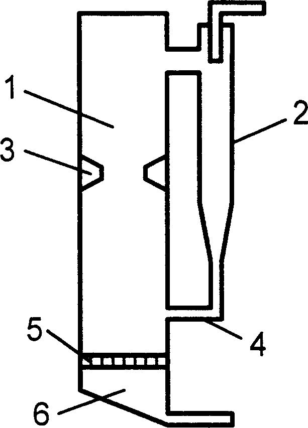
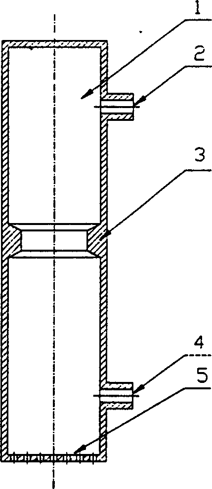
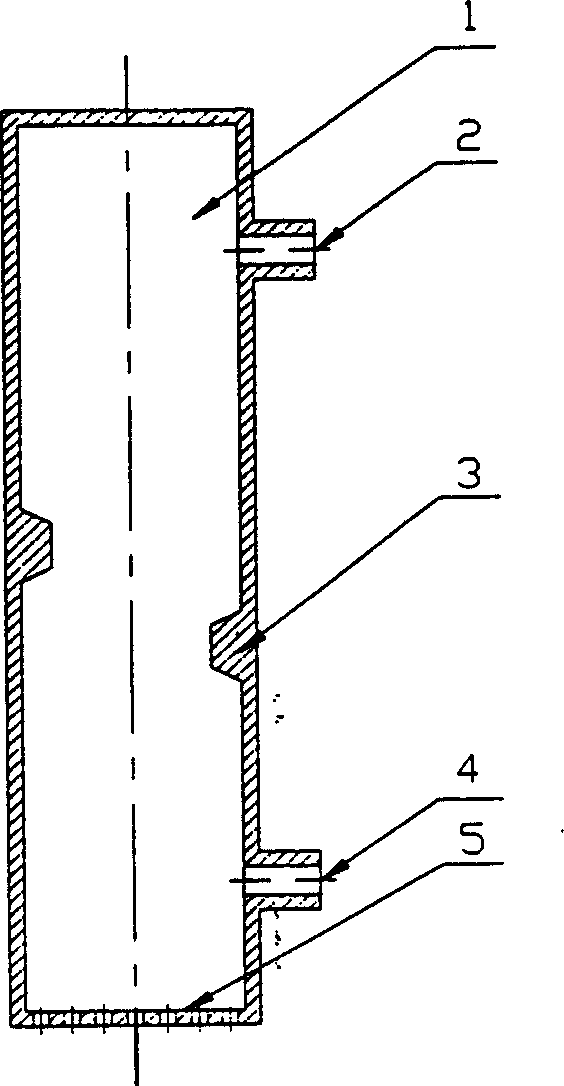
[0013] Such as figure 1 , figure 2 , image 3 , Figure 4 As shown, the present invention includes: a furnace 1, a cyclone separator 2, a throat 3, a return valve 4, an air distribution plate 5, and an air chamber 6. The specific improvements are as follows: a variety of The throat 3 is formed by the transverse partition wall structure protruding into the furnace, which divides the furnace 1 into several combustion chambers along the height. After adding the throat 3, multiple internal circulations appear in the furnace, and an external circulation is added to form a combined circulation. structure.

[0014] The shape of the throat 1 is various geometric shapes, such as: trapezoidal, rectangular, triangular, semicircular and Laval-shaped. Throat 1 is a single-stage throat or a multi-stage throat with two or more stages, and its positions can be directly opposite or staggered. The multi-stage throat is suitable for large-capacity circulating fluidized bed boilers, and the...


PUM


Abstract

A combined circulating fluidized bed boiler belongs to the field of mechanical engineering. The invention includes: a furnace, a cyclone separator, a throat, a return valve, and an air distribution plate, and the specific improvements are as follows: a plurality of transverse partition wall structures protruding into the furnace are arranged along the wall surface of the circulating fluidized bed to form a throat , the furnace is divided into several combustion chambers along the height, and after the throat is increased, multiple internal circulations appear in the furnace, and the external circulation is added to form a combined circulation structure. The invention can effectively improve the rising ability of the particle group in the furnace, reduce the density difference of the particles distributed along the bed height; increase the circulation amount of the particles near the wall of the furnace combustion chamber, and enhance the convective heat transfer between the particles and the wall; The residence time in the furnace strengthens combustion and promotes smoother feeding.

Description

technical field [0001] The invention relates to a fluidized bed boiler structure, in particular to a combined circulating fluidized bed boiler structure, which belongs to the field of mechanical engineering. Background technique [0002] Existing typical circulating fluidized bed boilers, through literature search, found that the patent applied by the Institute of Engineering Thermophysics, Chinese Academy of Sciences, the patent application number is: 94115512, the patent name is: circulating fluidized bed combustion device, the patent includes primary air Inlet, fuel inlet, secondary tuyere, furnace, high temperature gas-solid separator, split regulator, heat exchanger, tail convection flue, medium and low temperature gas-solid separator. Among them, the main section of the furnace is usually arranged in a vertical wall manner. This circulating fluidized bed structure has the following defects: the concentration of particles along the height of the bed drops sharply, and ...

Claims


Application Information

Patent Timeline
Patent Type & Authority Patents(China)
IPC IPC(8): F23C10/18
Inventor 缪正清陈永国田子平章明川熊天柱李俊
Owner SHANGHAI JIAOTONG UNIV
Why Eureka
Try Eureka