Cold rolling method and apparatus

A technology of operation device and running direction, applied in the driving device, metal rolling, metal rolling and other directions of metal rolling mill, can solve the problem of lack of fit and other problems, achieve the effect of high production volume, reduce investment and maintenance cost

Inactive Publication Date: 2005-11-09
VAI CLECIM (FR)
View PDF0 Cites 2 Cited by
  • Summary
  • Abstract
  • Description
  • Claims
  • Application Information

AI Technical Summary

Problems solved by technology

[0030] However, there are currently no plants suitable for the economical production of vari...

Method used


Image

  • Cold rolling method and apparatus
  • Cold rolling method and apparatus
  • Cold rolling method and apparatus

Examples


Embodiment Construction

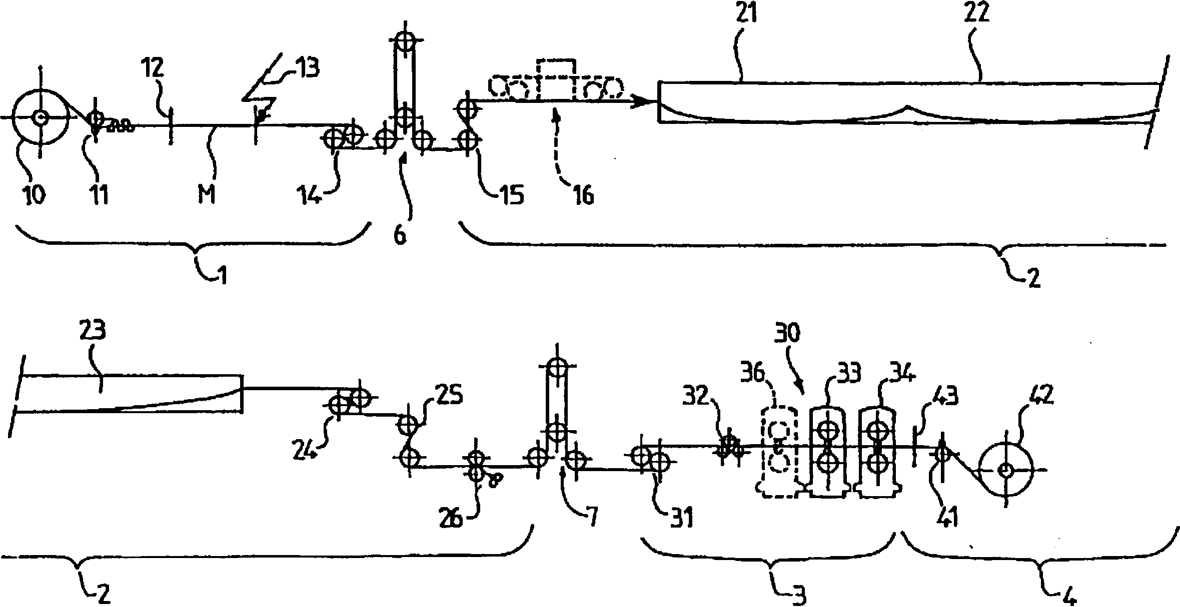
[0054] figure 1 A combined working device according to the invention is schematically shown, which comprises an inlet section 1 , a treatment section 2 , a cold rolling section 3 and an outlet section 4 of the metal strip in sequence along the longitudinal running direction of the metal strip.

[0055] In general, the entry and preparation section 1 of the strip M comprises a strip uncoiler 10 , a device 11 for straightening and flattening the strip, a cropping shear 12 and a welding machine 13 . In fact, once a coil has been fully uncoiled, a new coil should be placed on the uncoiler 10, the head of this new coil being connected to the tail of the previous coil, so as to ensure continuous deal with. To join two coils, their respective ends are first trimmed by crop shears 12 to form two parallel sides which are welded together by a welding machine 13 . The welding can also be performed by other suitable means. Crop shears 12 and welding machine 13 can also be assembled int...


PUM


Abstract

The invention relates to a method for rolling a metal band in a continuous line installation with coupling of the pickling and cold rolling processes. According to the invention, the composition of the pickling fluid is determined to allow the running of the band in the bath at a minimum speed of a few meters per minute, and similar running speeds are maintained in the pickling and rolling sections, during the operating phases, whereas the rolling conditions are determined in order to maintain the requested quality of the band at a minimum rolling speed that may be as low as 1 meter per minute.

Description

technical field [0001] The invention relates to a method and apparatus for cold rolling of metal strip, especially suitable for average annual production volumes, for example between 300,000 and 1 million tons. [0002] The invention is particularly suitable for descaling and rolling steel sheets or strips obtained by hot rolling or continuous casting of thin sheets. Background technique [0003] As is known, the production of metal products first requires the preparation of raw materials by ingot die casting or continuous casting, hot deformation by forging and / or hot rolling and cold deformation including various steps according to, for example, ferritic steel or austenitic The properties of metals such as solid steel and the products to be produced, such as ordinary steel, stainless steel and alloy steel, vary. [0004] Typically, the hot deformed product is peeled sequentially by descaling and cold rolled until the desired thickness is obtained, and may also be finished...

Claims


Application Information

Patent Timeline
IPC IPC(8): B21B1/28B21B1/38B21B45/06C23G3/02
CPCC23G3/02B21B45/06B21B2275/06B21B1/28B21B2001/383
Inventor 弗朗索瓦斯·勒鲁马克·瓦朗斯
Owner VAI CLECIM (FR)
Why Eureka
Try Eureka