Semi-bridge type PFC bus voltage equalization control method and device

A voltage equalization control, busbar technology, applied in output power conversion devices, sustainable manufacturing/processing, high-efficiency power electronic conversion, etc., can solve the problems of current command distortion, influence, and increased input current distortion.

Inactive Publication Date: 2005-11-23
LIANYUNGANG RES INST NANJING UNIV OF SCI & TECH
View PDF0 Cites 0 Cited by
  • Summary
  • Abstract
  • Description
  • Claims
  • Application Information

AI Technical Summary

Problems solved by technology

[0005] However, in this scheme, the voltage equalizing ring will affect the input current command, thereby distorting the current command, and finally increasing the THD (distortion degree) of the input current; the change of the regulator parameters of the current inner loop will also affect the voltage equalizing ring. The parameters of the gain and equalizing ring should also be adjusted accordingly

Method used


Image

  • Semi-bridge type PFC bus voltage equalization control method and device
  • Semi-bridge type PFC bus voltage equalization control method and device
  • Semi-bridge type PFC bus voltage equalization control method and device

Examples


Embodiment Construction

[0054] The present invention will be described in further detail below through specific embodiments and in conjunction with the accompanying drawings.

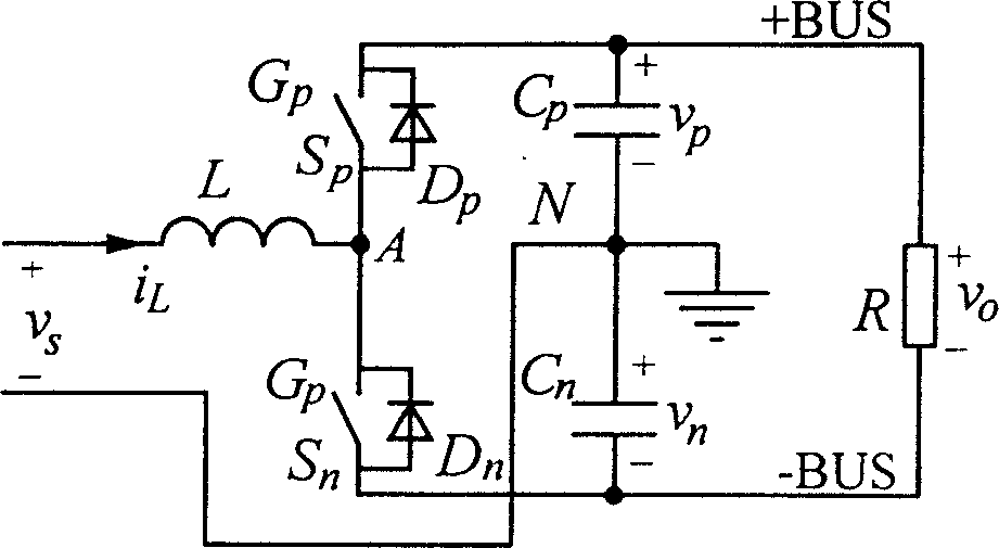
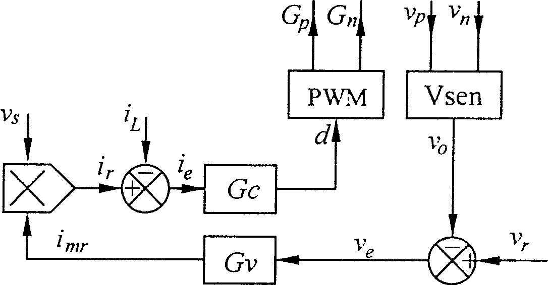
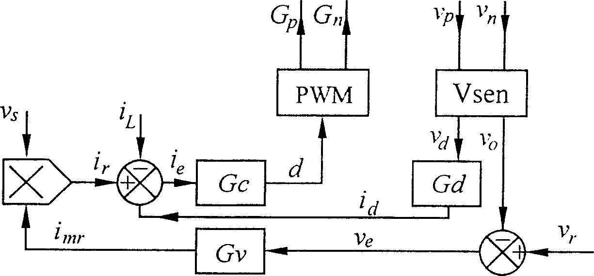
[0055] An improved positive and negative busbar voltage equalization control scheme is shown in Figure 4 . It includes the current regulator G c , voltage regulator G v , equalizing regulator G d ', pulse width modulation circuit PWM. The input terminal of the pulse width modulation circuit PWM is connected to the duty cycle signal d, and the output terminal has two channels, which are respectively used as the driving signal G p , G n The switching device S connected to the upper and lower bridge arms p , S n the control terminal.

[0056] Voltage regulator G v It is an outer loop, and its input terminal is connected to a comparator, and the input terminals of the comparator are respectively connected to the output voltage V o (V o =V p +V n ) and the output voltage command value V r ; voltage regulator G v the...


PUM


Abstract

This invention discloses a control method for PFC bus bar voltage-sharing of half-bridge type and its device, in which the positive and negative bus bar differential voltage is underground a proportion-integral-differential transformation, then the signal is directly superinposed on the duty ratio signal not to be front end of current loop. Even if the current loop exists, its variation would notinfluence the gain of equalizer ring, since the adjuster parameters of the internal current loop are adjusted independently and the parameters of the equalizer ring need to be adjusted once, and the equalizer ring would not influence current loop to generate little distortion to current order and THD of the current would not become large because of the qualizer ring.

Description

Technical field: [0001] The present invention relates to a half-bridge type (Half-Bridge Boost) PFC (power factor correction circuit) busbar voltage equalization control method and device. Background technique: [0002] The main circuit topology of the half-bridge PFC is shown in figure 1 , This circuit is simple with few components and high efficiency. generally used figure 2 The double-loop control shown, the outer loop is a voltage loop, the output voltage feedback is compared with the output voltage command, the error is passed through the PID (proportional-integral-derivative) regulator and the output is used as the command value of the input inductor current amplitude, which is realized by the inner loop The waveform of the input current tracks the waveform of the input mains, thereby realizing power factor correction. [0003] However, simply using figure 2 The control block diagram shown may have problems. In fact, the components of the upper and lower bridge a...

Claims


Application Information

Patent Timeline
Patent Type & Authority Patents(China)
IPC IPC(8): H02M1/12H02M1/14H02M1/42
CPCY02B70/126Y02B70/10Y02P80/10
Inventor 刘平于相旭
Owner LIANYUNGANG RES INST NANJING UNIV OF SCI & TECH
Why Eureka
Try Eureka