
Radiation source and device

A radiation source and irradiation area technology, which is applied in the field of irradiation devices, can solve problems such as the decrease of radiation current density, and achieve the effect of reliable heat dissipation

Inactive Publication Date: 2005-11-30
ADVANCED PHOTONICS INC
View PDF5 Cites 0 Cited by
  • Summary
  • Abstract
  • Description
  • Claims
  • Application Information

AI Technical Summary

Problems solved by technology

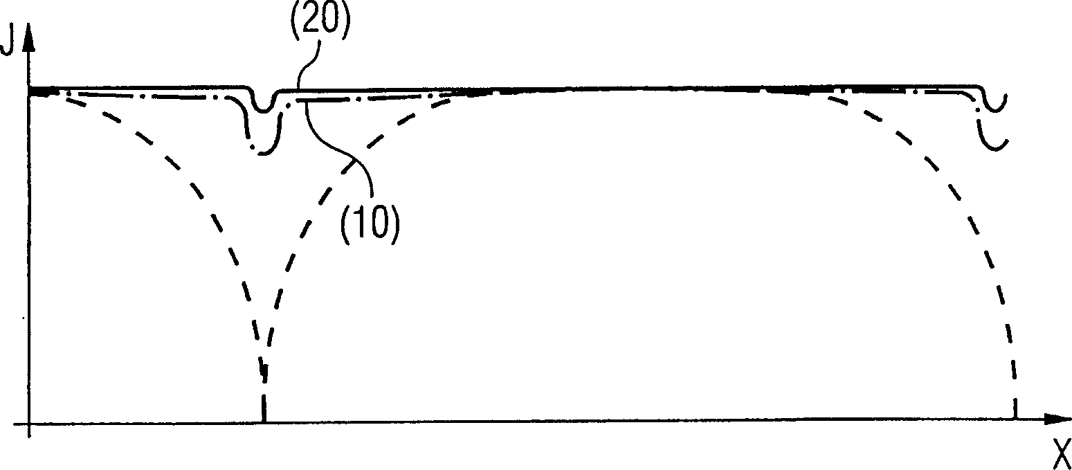
However, the above-mentioned problem of the drop in radiant current density at the end of the glass body of each halogen lamp near the lamp base has a very serious influence.
Therefore, for applications that strictly require the uniformity of the radiation flux density over the entire width of the working area, this type of irradiation device cannot be realized with the current radiation source structure.

Method used


Image

  • Radiation source and device
  • Radiation source and device
  • Radiation source and device

Examples


Embodiment Construction

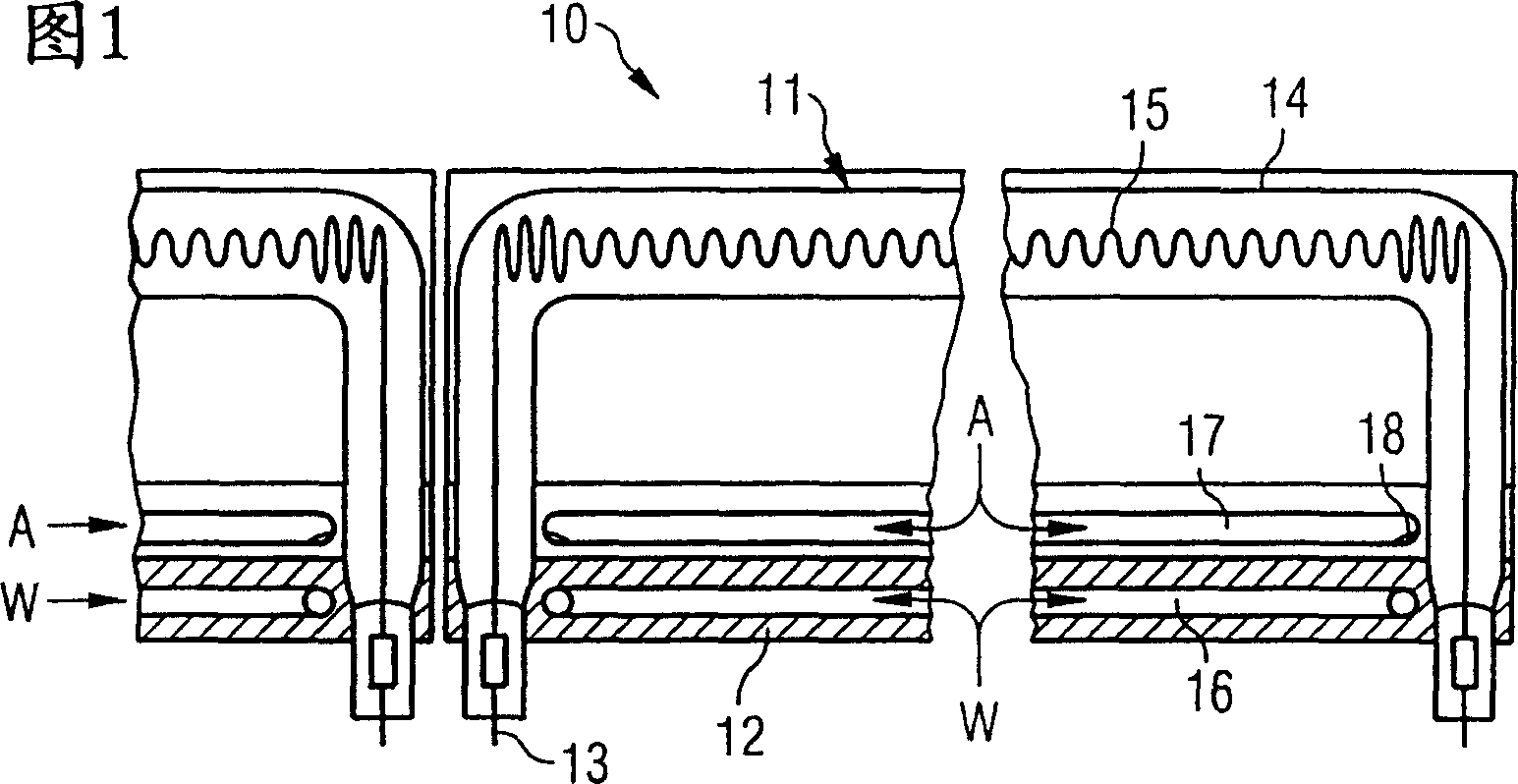
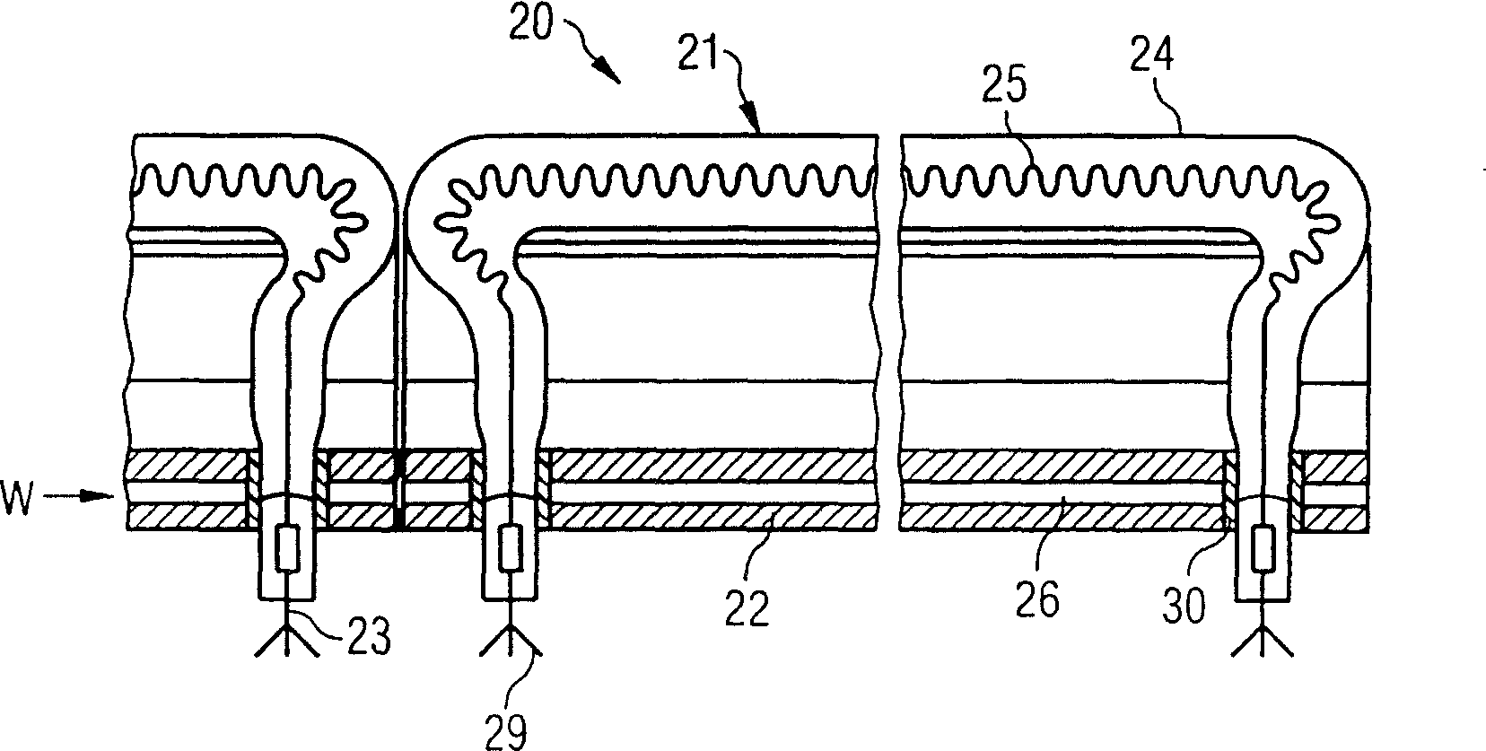
[0026] Figure 1 shows a part of a NIR-irradiation device 10 for technical purposes, which has a plurality of halogen filament lamps 11 arranged in sequence and aligned longitudinally with each other, each with a matching elongated reflector 12, which is formed by extruding Made of pressed aluminum profiles.

[0027] The basic structure of the reflector is known from EP0999724A2 by the applicant of the present invention and will therefore not be described here. In the following only special cooling devices are considered, which are arranged in or near the reflector.

[0028] As can be seen from the figure, the halogen filament lamp 11 has a tubular glass body 14 with a stud / connector 13 at each end and an elongated filament 15 distributed in the center of the glass body. The filaments are operated at high voltages and thus at high operating temperatures above 2500K, in particular above 2900K, and thus deliver radiation whose main radiation component is in the near-infrared reg...


PUM

PropertyMeasurementUnit
wavelengthaaaaaaaaaa

Abstract

Radiation source (11) for electromagnetic radiation the major effective component of which is in the near-infrared region, in particular in the wavelength region between 0.8 mum and 1.5 mum, to form an elongated irradiation zone, with an elongated halogen lamp (11) comprising a glass body (14) that has a tubular shape with bases at the ends and contains at least one spiral filament (15), and with an elongated reflector (12), such that the bases (13) of the halogen lamp are disposed in the region of the reflector surface or behind it with reference to the position of the halogen lamp, wherein the ends of the halogen lamp are bent around toward the reflector and the spiral filaments or at least one of them is made thicker or is more densely wound in the bent region of the glass body, in such a way that the radiation flux density of the radiation source is substantially constant in the long direction of the source, between the outermost points of the bases.

Description

technical field [0001] The invention relates to a radiation source and to an irradiation device produced with such a radiation source. Background technique [0002] From earlier patent applications by the applicant of the present invention, such as DE 19736462A1, WO99 / 42774 or P10024731.8 (unpublished), methods for surface treatment, material processing and composite material manufacturing using electromagnetic radiation are known, the main active ingredients of which are in the vicinity of In the infrared region, especially in the wavelength range from 0.8 μm to 1.5 μm. Achieving a wider irradiation field in a range of such applications is important to increase the productivity of the various methods. It is therefore known to use, as a radiation source, an elongated halogen lamp with an elongated reflector, which has a tubular glass body with at least one filament at the end formed as a socket. [0003] In the case of known radiation sources or lamp tubes with elongated e...

Claims


Application Information

Patent Timeline
Patent Type & Authority Patents(China)
IPC IPC(8): B29C35/08H01K1/28H01K7/00
CPCB32B2310/0825B29C35/08H01K7/00H01K1/28B29C2035/0822
Inventor R·高斯K·K·O·贝尔G·格泽尔T·贝格
Owner ADVANCED PHOTONICS INC
Learn More