Microfluidic devices incorporating improved channel geometries
A channel and fluid technology, applied in the field of microfluidic devices with improved channel geometry, can solve problems affecting system operation, capillary wall adsorption, etc.
- Summary
- Abstract
- Description
- Claims
- Application Information
AI Technical Summary
Problems solved by technology
Method used
Image
Examples
Embodiment Embodiment l
[0096] Embodiment embodiment 1: multi-sample analysis
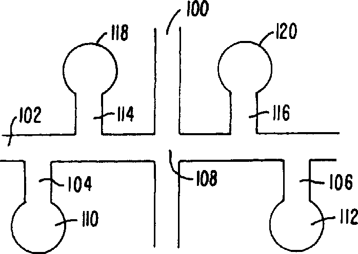
[0097] A device that can hold 16 samples, called LabChip TM , whose geometry is as image 3 As shown, it is made of a white crown glass substrate with a diameter of 100 mm and a thickness of 500 microns. The substrates used are compatible with most common flat-panel photographic devices commercially available. Channels 75 microns wide and 12 microns deep in the configuration shown were etched into glass substrates using standard planographic techniques. Another glass substrate, 5 inches on each side, was punched with holes corresponding to the ends of the individual channels. The two substrates are thermally bonded to form the channel and library structures shown. A 22.4 mm x 37 mm sized device was cut from this large piece of material.
[0098] Preparation of screening buffer: Weigh 2.5g of GeneScan Polymer (Perkin Elmer Corp.), 0.5g of Gene Analysis Buffer (Perkin Elmer Corp.) and 2.5ml ...
Embodiment 2
[0110] The results of the initial separation using this method are shown in Image 6 . Apparently, this method using capillary electrophoresis achieves higher resolution while significantly shortening the time. Moreover, no loss of resolution occurred throughout the separation of 16 samples. Embodiment 2: Detection of continuous sample cross-contamination
[0111]In order to determine whether cross-contamination of samples occurred during continuous operation in the device, two different samples of nucleic acid fragments and one sample of pure buffer were continuously tested and the results of contamination were detected.
[0112] Each of the above 16 library sets was spiked with PCR markers, HAEIII cleaved PhiX174, or pure buffer. Loading was performed according to the sequential injection order of each pool. Record the fluorescence data over time for each run.
[0113] Figure 7A , 7B and 7C are graphs of sequential injection of PCR marker, PhiX174 / HAEIII and buffer b...
Embodiment 3
[0113] Figure 7A , 7B and 7C are graphs of sequential injection of PCR marker, PhiX174 / HAEIII and buffer blank. Figure 7B It was shown that no abnormal fluorescent peaks were detected indicating bleeding into the PhiX174 / HAEIII assay from the previous PCR marker assay. in addition, Figure 7C showed that no cross-contamination from previous DNA-containing samples was detected even in the pure buffer assay. Example 3: Narrow channel injection
[0114] Prepare a microfluidic device as described in Example 1, the geometric structure of its channel is as follows Figure 5 As shown, the difference is that the width of all channels in the device is reduced to 30 microns, while the channel depth remains at about 12 microns. Use it to match the geometric structure in Example 1 such as Figure 4 Comparison of microfluidic devices shown but with channel widths around 70 μm. The lengths of the separation channels in the two devices are substantially equal.
[0115] Both devices...
PUM
| Property | Measurement | Unit |
|---|---|---|
| Width | aaaaa | aaaaa |
Abstract
Description
Claims
Application Information
 - R&D
- Intellectual Property
- Life Sciences
- Materials
- Tech Scout
- Unparalleled Data Quality
- Higher Quality Content
- 60% Fewer Hallucinations
Browse by: Latest US Patents, China's latest patents, Technical Efficacy Thesaurus, Application Domain, Technology Topic, Popular Technical Reports.
© 2025 PatSnap. All rights reserved.Legal|Privacy policy|Modern Slavery Act Transparency Statement|Sitemap|About US| Contact US: help@patsnap.com


