Design and manufacture of low-inductance bus
A low-inductance busbar and negative busbar technology, applied in busbar/circuit layout, output power conversion devices, electrical components, etc., can solve complex methods, it is difficult to ensure long-term reliable operation of the inverter, reduce low-inductance Busbar etc.
- Summary
- Abstract
- Description
- Claims
- Application Information
AI Technical Summary
Problems solved by technology
Method used
Image
Examples
Embodiment 1
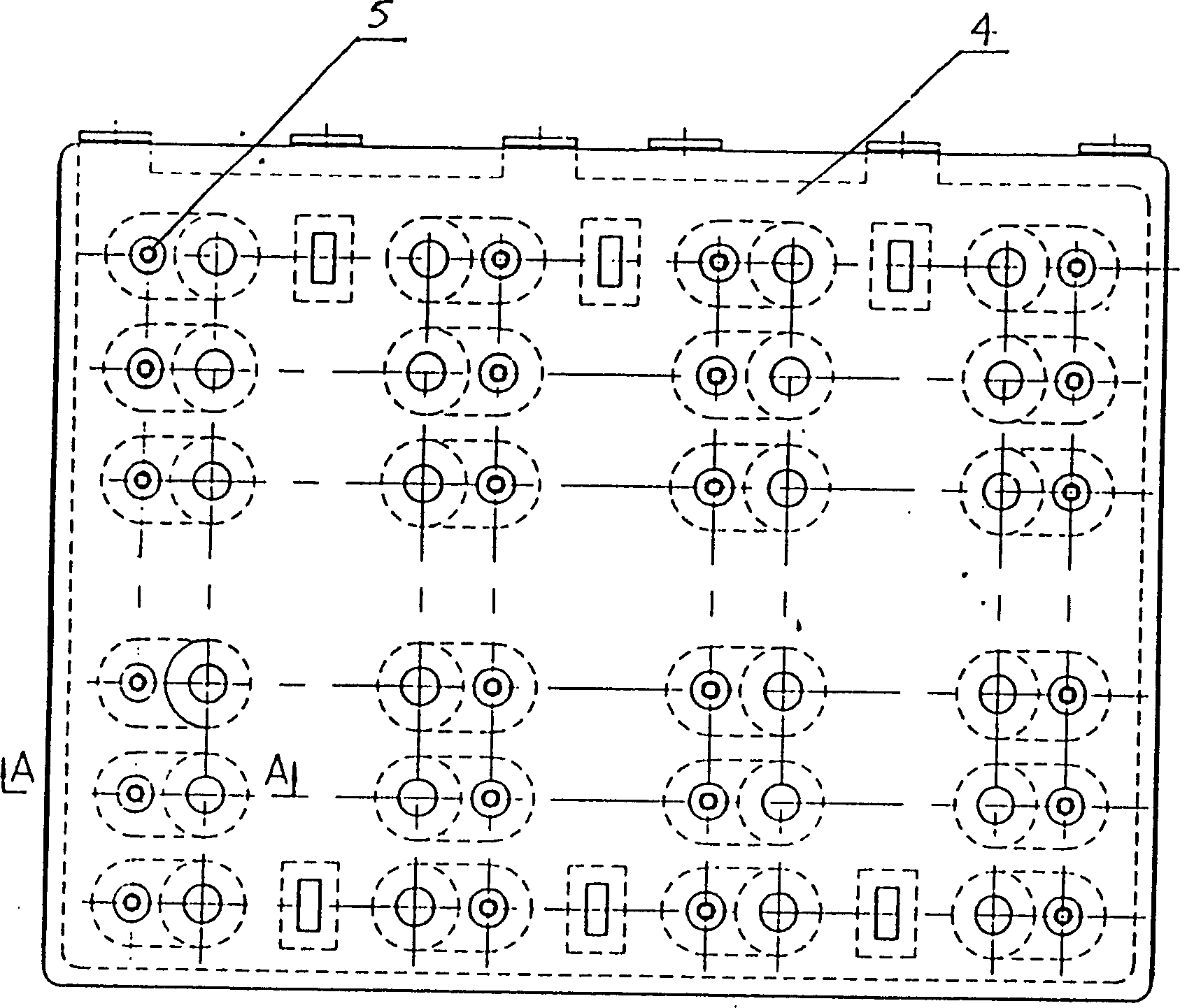
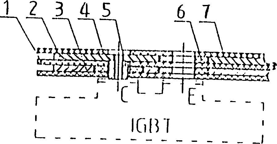
[0032] attached figure 1 , 2 For the given low-sensitivity busbars, the positive and negative busbars are made of electrolytic copper plates or aluminum plates less than 2mm, and the intermediate insulation layer is insulated by epoxy boards FR4 or flexible substrates (such as LPE3'-FR) less than 1.5mm Composed of materials, the outer insulating layer is composed of epoxy board under 2mm; the connection between the low-sensitivity busbar and the IGBT components is carried out through conductive copper columns riveted on the positive and negative busbars; each adjacent two layers Prepregs that act as a bond are stacked between
[0033] (7): At the same time, an insulating plug 6 is added between the positive and negative busbars and the conductive copper column.
[0034] The above-mentioned low-sensitivity busbar adopts the method of adding insulating plugs in the structural form, and makes full use of the glue flow characteristics of the prepreg to fully bond the insulating ...
Embodiment 2
[0035] Embodiment 2 (see attached image 3 , 4 ) and Example 3 (see attached Figure 5 , 6 )
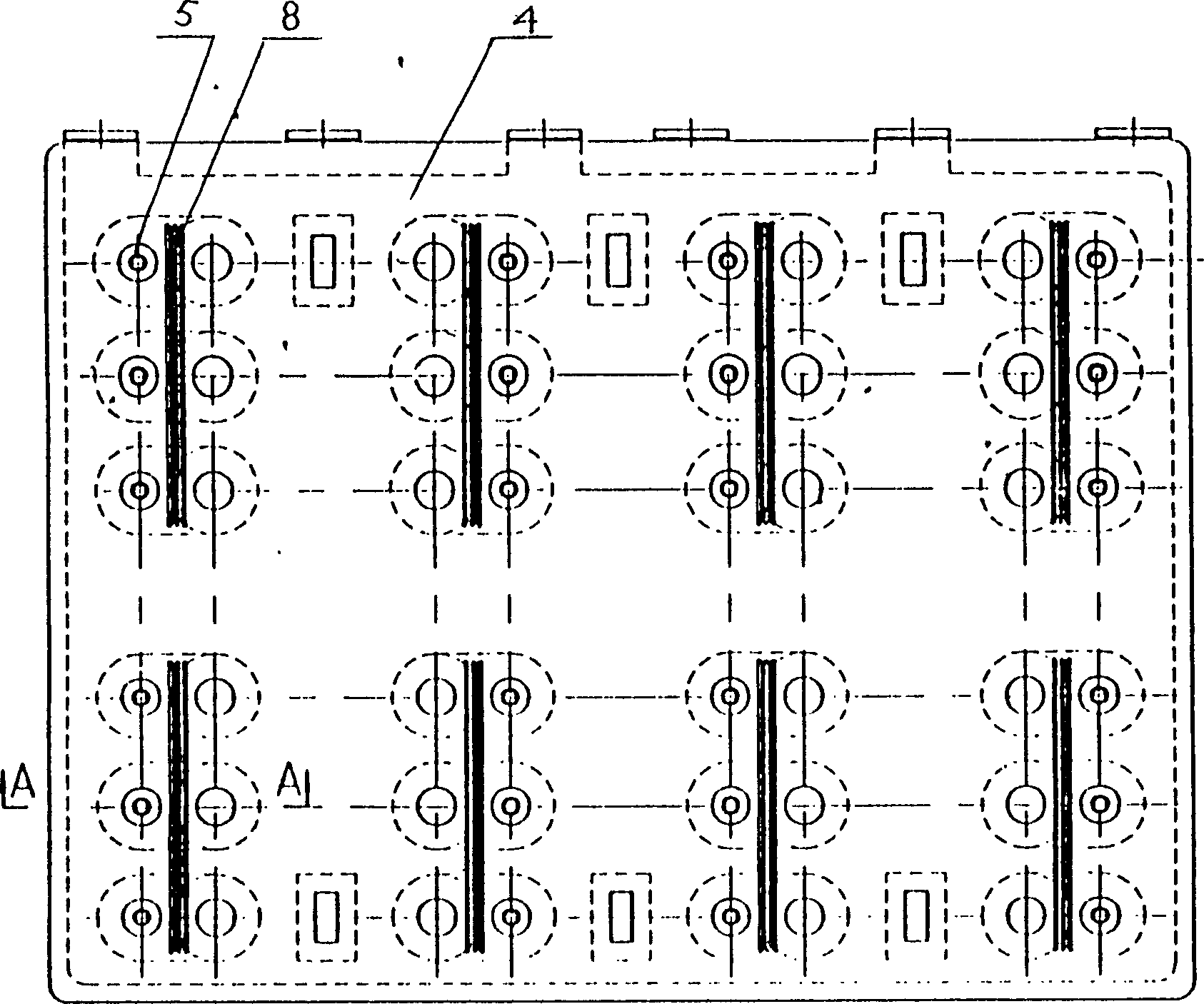
[0036] These two embodiments are actually two improvements to Embodiment 1, and their common purpose is to increase the creepage distance between C and E poles. Wherein the method that embodiment 2 adopts is the way that does not increase any additional accessories, promptly mills out a certain number of small grooves 8 on the outer layer insulating layer 4, makes collector, emitter two poles by these 2-5 small grooves The creepage distance between them is moderately increased.
Embodiment 3
[0037] Embodiment 3 is to add a raised creepage isolation plate 9 on the outer insulating layer 4 between the collector and the emitter poles, and to pass through the isolation plate 9 or additionally add a small milling plate on the isolation plate 9. The groove 8 increases the creepage distance between the collector and the emitter (of course, the increased creepage distance of this solution is greater than that of Embodiment 2).
[0038] It is due to the adoption of the attached image 3 , 4 And attached Figure 5 , 6 These two improvements enable the busbar to expand the creepage distance between the collector and the emitter without changing the specification and shape, so that the busbar can be used in applications with a working voltage greater than 1500VDC.
[0039] The specific production methods of the low-sensitivity busbars shown in the above examples 1-3 should be as follows: blanking - drilling, milling, punching and bending processing - riveting welding - cle...
PUM
 Abstract
Description
Claims
Application Information
 - R&D
- Intellectual Property
- Life Sciences
- Materials
- Tech Scout
- Unparalleled Data Quality
- Higher Quality Content
- 60% Fewer Hallucinations
Browse by: Latest US Patents, China's latest patents, Technical Efficacy Thesaurus, Application Domain, Technology Topic, Popular Technical Reports.
© 2025 PatSnap. All rights reserved.Legal|Privacy policy|Modern Slavery Act Transparency Statement|Sitemap|About US| Contact US: help@patsnap.com


