Integrated solid oxide fuel cell and reformer

A fuel cell and battery technology, applied in the direction of solid electrolyte fuel cells, fuel cells, fuel cell additives, etc., can solve problems such as sealing that cannot withstand thermal stress and high temperature resistance

Inactive Publication Date: 2000-12-13
ACUMENTRICS
View PDF5 Cites 9 Cited by
  • Summary
  • Abstract
  • Description
  • Claims
  • Application Information

AI Technical Summary

Problems solved by technology

Although the design is simple, it requires a large number of high-temperatu

Method used


Image

  • Integrated solid oxide fuel cell and reformer
  • Integrated solid oxide fuel cell and reformer
  • Integrated solid oxide fuel cell and reformer

Examples


Embodiment Construction

[0047] best practice

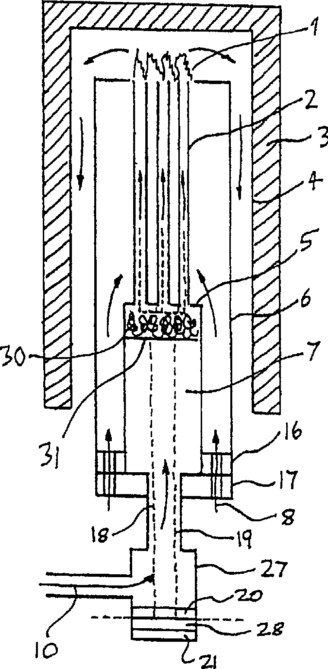
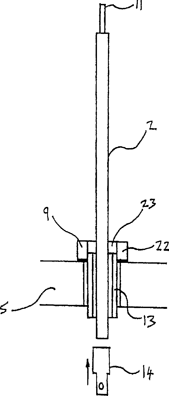
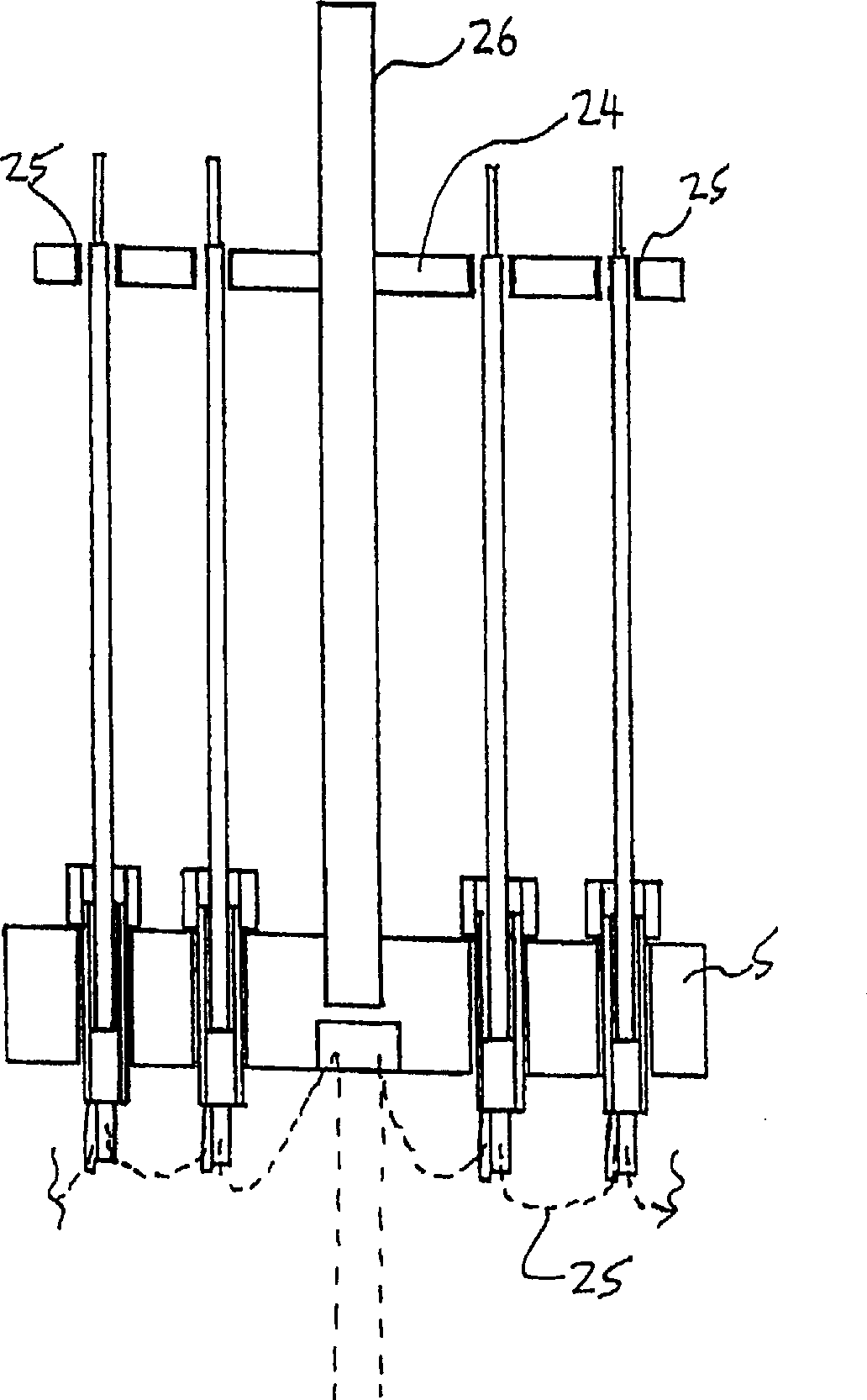
[0048] refer to figure 1 , electricity is generated in the plurality of tubular fuel cells 2 when fuel flows through the inside of the tubular fuel cells and air flows through the outside thereof. Fuel cells of this structure are well known in the art, the article "SOFC power generation system made of extruded tubes with a diameter of 2 mm" (Author: K.Kendall, T.W.J.Longstaff, Second European Solid Fuel Cell Forum, Luceme, Sweden , May 6-10, 1996, p. 195) are very suitable as described in fuel cells. The fuel cells are mounted on the base plate 5 forming the top of the reforming chamber 7 . Inside the reforming chamber is the reforming catalyst, which converts the carbon-containing fuel into a hydrogen-rich mixture.

[0049] Air enters the system through perforated rings 16, 17, which are mounted on the outside of the aforementioned chambers. Air flows through the fuel cell, burns with converted fuel at the end of the fuel cell, and exits the tubes. ...


PUM


Abstract

Described is an apparatus for generating electrical power. The apparatus has a plurality of tubular solid oxide fuel cells (2) contained in a reaction chamber (40). Fuel cells (2) are secured at one end thereof in a manifold block (51), the other ends thereof passing freely through apertures (63) in a baffle plate (47) to reside in a combustion chamber (41). Reaction gases are supplied to the insides of the tubular fuel cells (2) from a plenum chamber (42) below the manifold block (51) and to the reaction chamber (41) surrounding the outsides of the fuel cells through an annular inlet path, which may include a reformation catalyst. The gases inlet path to the plenum chamber (42), and the annular inlet path surrounding the reaction chamber, are both in heat conductive relation with the reaction chamber and the combustion chamber, and raise the gases to formation and reaction temperatures as appropriate.

Description

technical field [0001] This invention relates to power generation plants, and in particular to solid oxide fuel cells (SOFCs) for such plants. Background technique [0002] SOFC is a device that generates direct current through the direct electrochemical action of fuel (such as hydrogen, natural gas, coal gas, or other hydrocarbon-based fuel) and oxidant (such as air). SOFCs contain a conductive oxygen-ion electrolyte (now based on stabilized zirconia) that separates the air electrode (cathode) from the fuel electrode (anode). The fuel is oxidized at the anode and the electrons are absorbed by the cathode after being released to the external circuit. The cathodic reaction causes the oxidant gas to be reduced to oxygen ions, which then migrate across the oxygen ion-conducting electrolyte to the anode. The movement of electrons in an external circuit generates electromotive power (typically 1 volt per cell). When a load is applied to the battery, a current is generated, whi...

Claims


Application Information

Patent Timeline
IPC IPC(8): H01M8/04007
CPCY02E60/521Y02E60/525Y02E60/50
Inventor 奈杰尔·马克·萨梅斯
Owner ACUMENTRICS
Why Eureka
Try Eureka