Spur gear extrusion concave die

The technology of spur gear and concave die is applied to the extrusion die of spur gear extrusion. In the field, the effect of reducing the influence of friction and easy forming

Inactive Publication Date: 2006-11-08
HEFEI UNIV OF TECH
View PDF0 Cites 0 Cited by
  • Summary
  • Abstract
  • Description
  • Claims
  • Application Information

AI Technical Summary

Problems solved by technology

[0003] The problem to be solved by the present invention is to avoid the shortcomings of the above-mentioned prior art, and to provide a spur gear extrusion with small extrusion force, easy filling of the tooth-shaped part, easy wear of the involute of the concave die, and long service life. die

Method used


Image

  • Spur gear extrusion concave die
  • Spur gear extrusion concave die
  • Spur gear extrusion concave die

Examples


Embodiment Construction

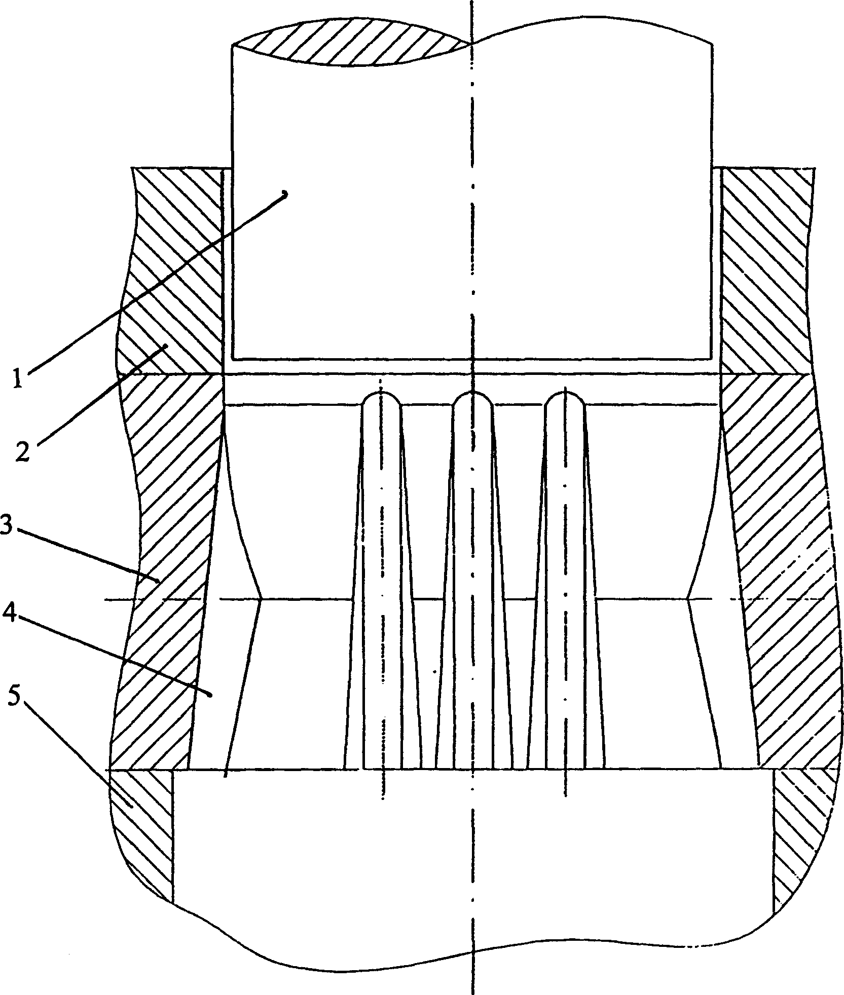
[0020] See attached figure 1 , The die in this embodiment is from the blank inlet to the formed metal outlet, followed by the guide section 2, the forming section 3, the support section 4 and the die backing plate 5. In the guide section 2 of the die, the diameter of the die entrance should be larger than the diameter of the pitch circle of the forming gear and smaller than the diameter of the addendum circle of the forming gear, and the diameter of the blank should be set accordingly. The unilateral gap between the punch 1 and the guide section 2 of the concave mold is not more than 0.15mm. In order to make the support more effective, the forming section 3 and the support section 4 should be designed as an integral structure.

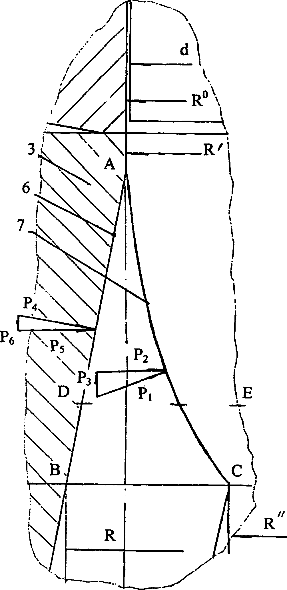
[0021] figure 2 As shown, the end of the die forming section 3 (the B-C section is shown in the figure), the geometric shape and size of the inter-tooth gap are consistent with the tooth profile of the formed gear plane projection. Including the roo...


PUM


Abstract

The extrusion die for spur gears is characterized in that the diameter of the die entrance is larger than the diameter of the pitch circle of the forming gear and smaller than the diameter of the addendum circle of the forming gear; in the forming section, the addendum forms an inwardly inclined wall, and the axis of the tooth root The line is a straight line; the geometric shape and size of the gap between the teeth at the end of the forming section is consistent with the tooth profile projected on the plane of the forming gear; The tangent point of the side wall; on any other cross-section of the forming section except the end of the forming section, except for the top arc of the tooth profile between the tangent points of the side walls between the teeth, the geometric shape and size of the rest of the teeth are uniform It is consistent with the corresponding part at the end of the forming section. The extrusion force required for metal forming in the invention is small, the tooth-shaped part is easy to fill, the involute line of the concave die is not easy to wear, and the service life is long.

Description

Technical field: [0001] This invention relates to extrusion dies for metal extrusion. More particularly, an extrusion die for the extrusion of spur gears, in particular. Background technique: [0002] The main problems of the spur gear extrusion dies commonly used at present are the large extrusion force during the extrusion molding process, the difficulty of filling the tooth profile, and the large wear of the involute part of the concave die. Invention content: [0003] The problem to be solved by the present invention is to avoid the shortcomings of the above-mentioned prior art, and to provide a spur gear extrusion with small extrusion force, easy filling of the tooth-shaped part, easy wear of the involute of the concave die, and long service life. die. [0004] The technical scheme adopted in the present invention is: [0005] A, described concave die, its entrance diameter is greater than forming gear indexing circle diameter, is less than forming gear addendum ci...

Claims


Application Information

Patent Timeline
Patent Type & Authority Patents(China)
IPC IPC(8): B21C25/02
Inventor 刘永熙王强杜晓东
Owner HEFEI UNIV OF TECH
Why Eureka
Try Eureka