Check patentability & draft patents in minutes with Patsnap Eureka AI!

Position regulator of non-contact supported fast rotary rotor, esp. spinning rotor

A technology for adjusting the position of the device and the rotor, which is applied in the processing of textile materials, electromechanical devices, textiles and papermaking, etc., can solve the problems of the device can not be compensated, the non-uniformity of the rotor material, etc., to achieve the effect of simple cost and reduced power reception

Inactive Publication Date: 2006-11-22
SAURER GERMANY GMBH & CO KG
View PDF3 Cites 0 Cited by
  • Summary
  • Abstract
  • Description
  • Claims
  • Application Information

AI Technical Summary

Problems solved by technology

Every unbalance not originating from a measurable geometric error, for example due to inhomogeneity of the rotor material or due to adhering debris which may collect in the rotor grooves of textile rotors, cannot be compensated with the device described in DE3120691A1

Method used


Image

  • Position regulator of non-contact supported fast rotary rotor, esp. spinning rotor
  • Position regulator of non-contact supported fast rotary rotor, esp. spinning rotor
  • Position regulator of non-contact supported fast rotary rotor, esp. spinning rotor

Examples


Embodiment Construction

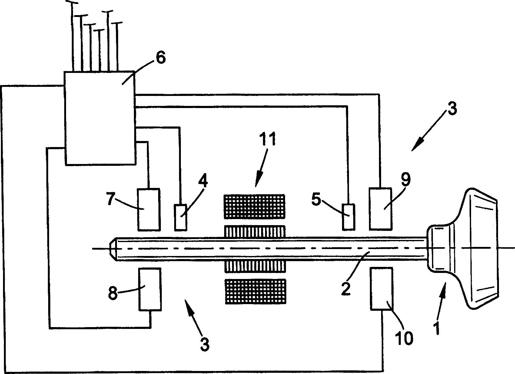
[0035] Will be attached figure 1 The textile rotor 1 shown above is supported on the rotor shaft 2 with magnetic bearings. The position of the rotor shaft 2 is detected by a sensor device having sensors 4, 5 by a method known per se. The sensor device continuously generates a detection signal, inputs the detected signal to the control device 6, and outputs an actuator signal from the control device. The actuator elements 7, 8, 9, 10 belonging to the sensors 4, 5 have magnetic coils and are used to hold the textile rotor 1 in the desired position. The driving device 11 gives the textile rotor 1 a rotational movement. In order to operate the actuator elements 7, 8, 9, 10, the control device 6 uses the control voltage U ST Load the actuator device. Accordingly, for reasons of simplification, the sensors and actuator elements that are not shown are installed at 90° offset from the sensors 4, 5 and actuator elements 7, 8, 9, 10 in the rotation direction of the textile rotor 1. For the...


PUM


Abstract

The invention relates to a device for adjusting the position of a fast-turning rotor supported without contact, in particular a textile rotor, having a sensor device for continuously generating a rotor position signal and a control device (6) for processing the rotor position signal, wherein the control The device (6) continuously outputs the control signal to the actuator device which influences the rotor position. The control device (6) is designed in such a way that the slope of the curve of the additional signal, from which the control variable is derived, is limited by the maximum value and can cause a problem for the execution if the rotor position signal has a relatively high vibration frequency and at the same time a small phase error. A decrease in the vibration amplitude of the additional signal of the mechanism. With the device according to the invention, low energy consumption, extended controllability and relatively high operating safety can be achieved in a simple manner. The device according to the invention can advantageously be used on a magnetically supported textile rotor (1).

Description

Technical field [0001] The invention relates to a textile rotor used for a fast-rotating rotor axial position adjustment device without contact support. Background technique [0002] It is known in many structures to use passive non-contact support or non-contact active support with adjustment devices for position stabilization or for vibration damping. [0003] DE3323648A1 shows, for example, a magnetic support comprising an actuator with electromagnetic coils. The magnetic support has two mutually offset supporting bearing parts in the direction of the rotation axis of the rotor. For the two directions perpendicular to the rotor axis of rotation and each other, the movement deviation between the instantaneous position of the axis of rotation and the nominal position should be calculated and adjusted by magnetic control. In addition, the deflection movement of the rotor around the two perpendicular directions parallel to the axis of rotation is calculated and generated to genera...

Claims


Application Information

Patent Timeline
IPC IPC(8): G05D3/12G05D13/62H02K7/09F16C39/06
CPCF16C32/0451F16C2340/18D01H4/12
Inventor N·科宁
Owner SAURER GERMANY GMBH & CO KG
Features
  • R&D
  • Intellectual Property
  • Life Sciences
  • Materials
  • Tech Scout
  • Unparalleled Data Quality
  • Higher Quality Content
  • 60% Fewer Hallucinations
Learn More