
Air inlet structure for engine

An air intake structure and engine technology, applied in the direction of intake muffler, fuel air intake, combined air filter and muffler, etc., can solve the loss of layout flexibility, ensure that the installation location is easy to add restrictions, Large-scale assembly components and other issues

Inactive Publication Date: 2006-12-27
SUZUKI MOTOR CORP
View PDF4 Cites 0 Cited by
  • Summary
  • Abstract
  • Description
  • Claims
  • Application Information

AI Technical Summary

Problems solved by technology

[0005] In addition, by using resin technology to integrate the surrounding parts of the air intake system, although the number of parts and clearances can be reduced, on the other hand, it may lead to an increase in the size of the assembly and loss of layout flexibility.
For example, it is well known that by using resin molding technology, there is a prior art that integrates the air cleaner volume part, the combustion chamber part, and the surge tank part (for example, refer to Japanese Patent Application Laid-Open No. 9-137729), and the air Filter, resonator and engine cover three constitute the prior art (for example, refer to Japanese Patent Application Laid-Open No. 2001-234821), but no matter what kind of technology, it is difficult to avoid the enlargement of assembly components, and it is difficult to ensure The disadvantage that it is easy to add restrictions on the installation position, this disadvantage becomes more significant with the reduction of the engine room

Method used


Image

  • Air inlet structure for engine
  • Air inlet structure for engine
  • Air inlet structure for engine

Examples


Embodiment Construction

[0027] Hereinafter, the air intake structure of the engine according to the embodiment of the present invention will be described using the attached drawings.

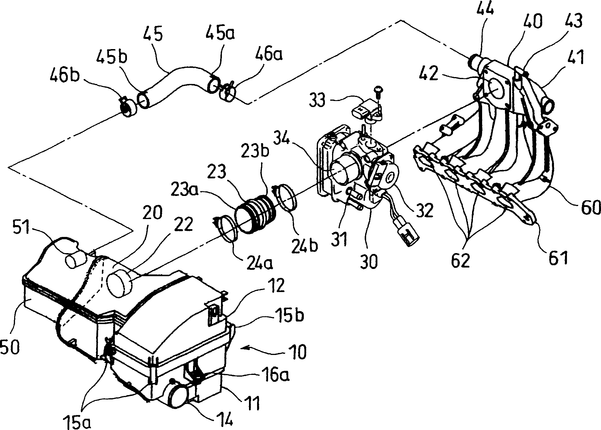
[0028] figure 1 It is a schematic diagram showing the intake structure of the engine according to the embodiment of the present invention. As shown in the figure, the air filter 10, the throttle body 30, the surge tank 40 and the intake branch pipe 60 are connected to form an air intake system for sucking air into the engine from the outside of the vehicle. At this time, as known to those skilled in the art, the air filter 10 is used to prevent dust in the air from entering the engine to accelerate wear, and to reduce intake noise. In addition, the engine output is controlled by controlling the amount of intake air by the throttle body 30 . In addition, the surge tank 40 functions as a collection part connecting the throttle body 30 and the intake branch pipe 60 , and prevents interference of each cylinder while prev...


PUM


Abstract

Provided is an intake structure for an engine capable of being compactly installed in a limited space and satisfying desired engine characteristics. This intake structure is the one for the engine which connects an air cleaner 10 with a serge tank 40 through a throttle body 30, and connects the serge tank 40 with an inlet port provided at a cylinder head through an intake manifold 60. The serge tank 40 is disposed at a side of the cylinder head and has a joint portion 44 at a side surface, and a resonator 50 communicated with the serge tank 40 through a hose 45 attached at the joint portion 44 is disposed on a head cover of the engine. The air cleaner 10 and the resonator 50 are integrally formed, thus saving the space, reducing the number of parts, and improving ease of assembly of the engine.

Description

technical field [0001] The present invention relates to the air intake system structure of an automobile engine. Background technique [0002] Recently, in automobiles, in order to improve engine performance, there is a tendency to increase the size of the intake structure, so that more air can be sent into the cylinder and the volumetric efficiency can be improved. However, in recent years, with the advancement of vehicle control, various additional equipment is installed, so the space in the front, rear, left and right of the engine room has become narrow. When installing an air intake structure on a vehicle with a small engine room, it is sometimes difficult to secure an appropriate amount of air intake. For this reason, when arranging the intake structure in the engine room, while satisfying the required engine performance, useless structural elements and gaps were deleted as much as possible to improve the layout. [0003] Furthermore, ...

Claims


Application Information

Patent Timeline
Patent Type & Authority Patents(China)
IPC IPC(8): F02M35/10F02M35/12F02M35/14
Inventor 中村隆泷本裕二
Owner SUZUKI MOTOR CORP
Learn More