Retarder

A technology of reducer and rotor disk, applied in the direction of brake, electric brake/clutch, asynchronous induction clutch/brake, etc., can solve the problem of weak braking force and achieve the effect of improving mechanical stability

Inactive Publication Date: 2007-01-24
洛塔尔·克洛夫特 +2
View PDF4 Cites 0 Cited by
  • Summary
  • Abstract
  • Description
  • Claims
  • Application Information

AI Technical Summary

Problems solved by technology

The disadvantage of this known device is that the braking force is too weak, because the coils are only approximately distributed on the semicircle of the rotor

Method used


Image

  • Retarder
  • Retarder
  • Retarder

Examples


Embodiment Construction

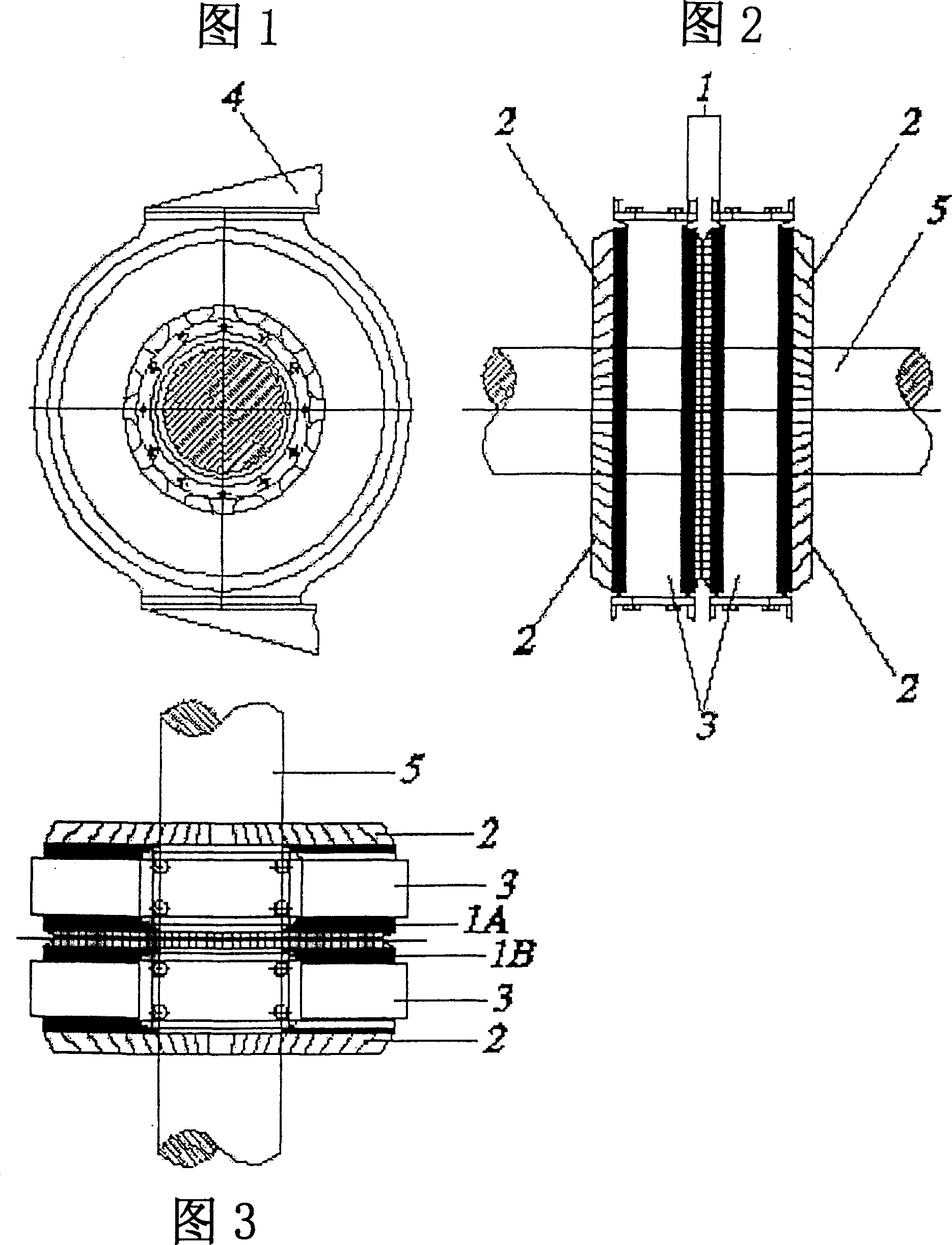
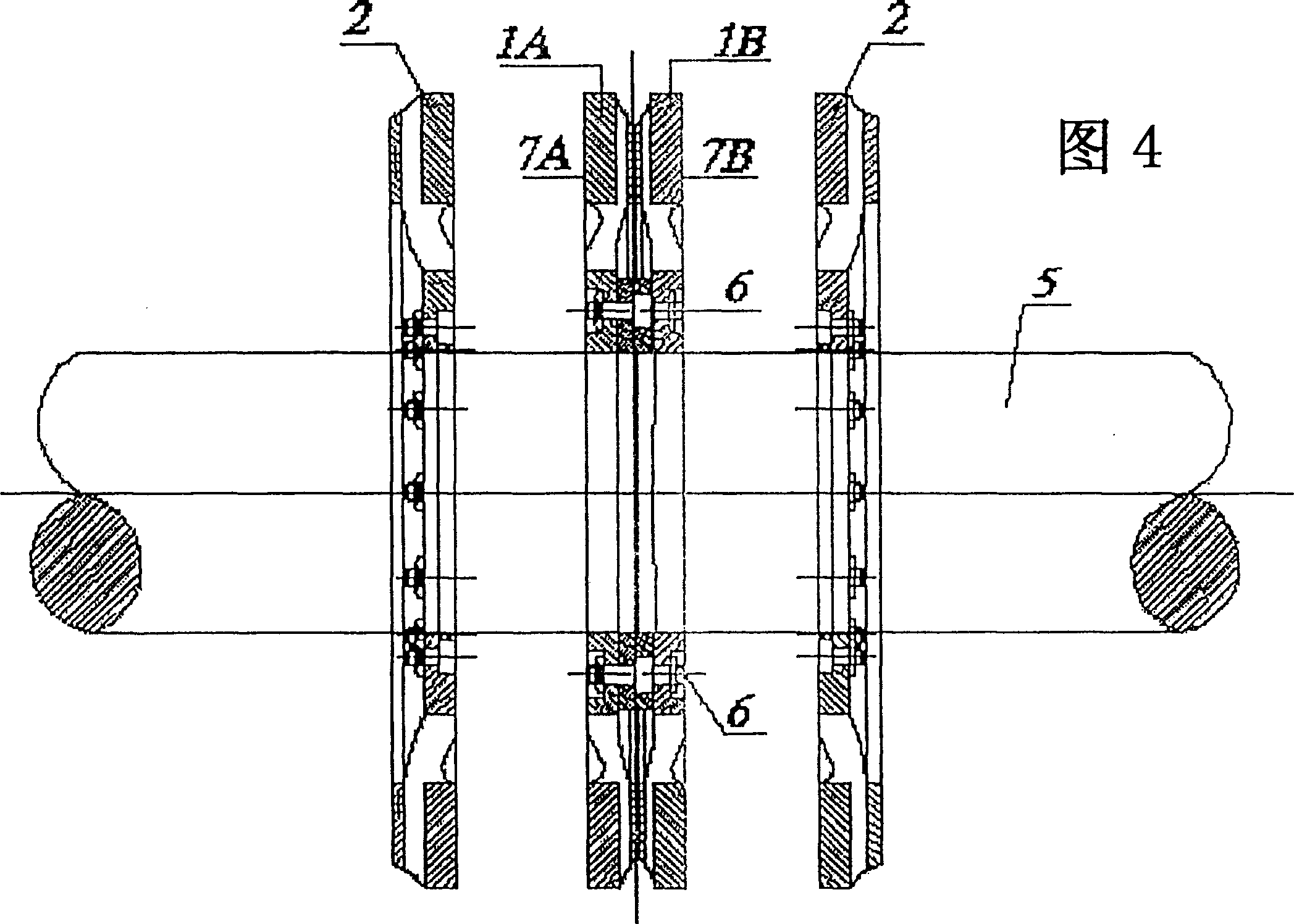
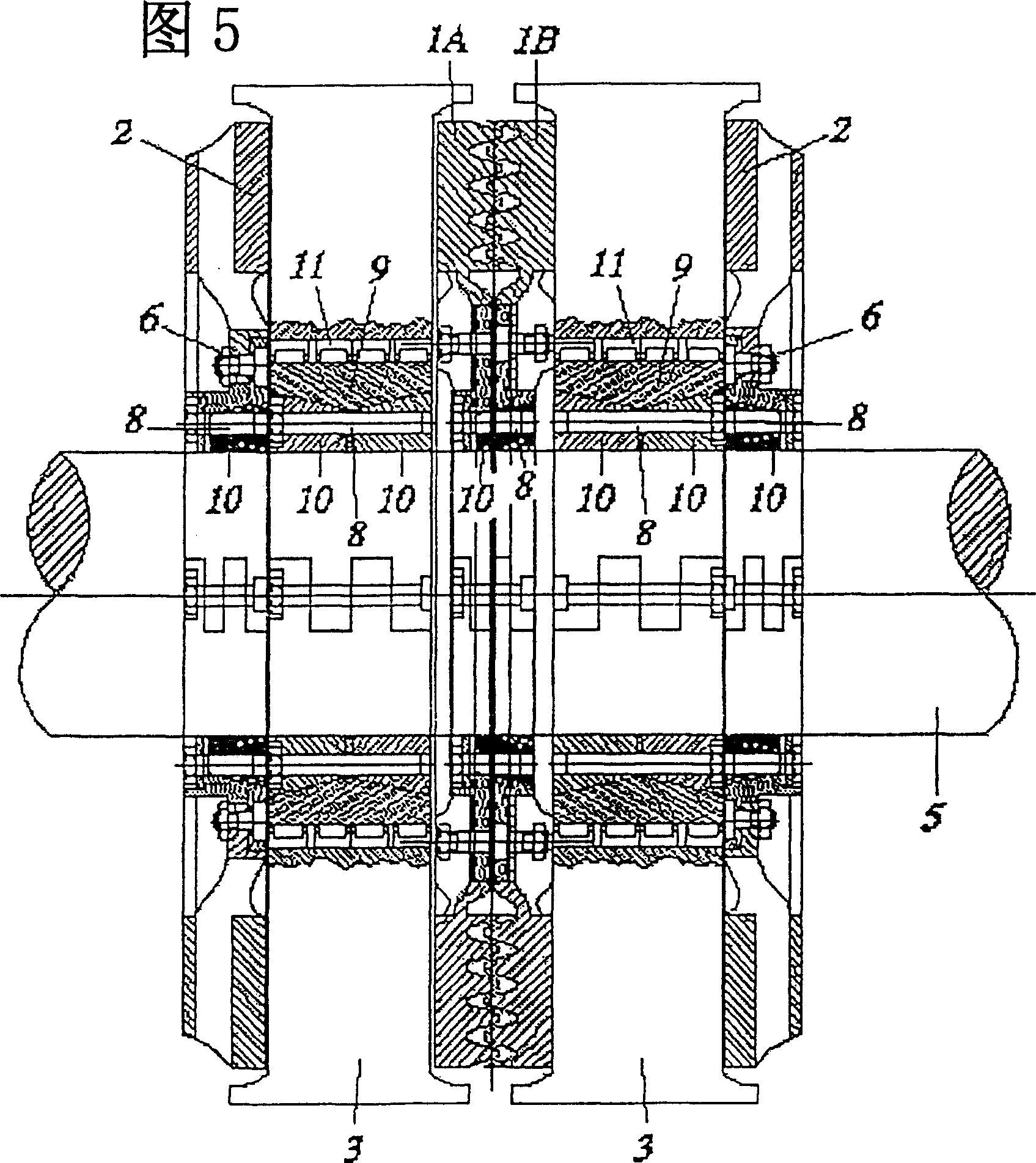
[0029] The retarder shown in FIG. 1 has a number of electromagnetic coils mounted on an annular coil former or stator 3 concentrically with one axle 5 of the rail vehicle. Within a small distance before the coil poles, on both outer sides of the stator 3 there is an outer rotor disk 2 , which is connected in a rotationally fixed manner to the axle 6 . The stator housing is in two parts, so that an intermediate rotor disk 1 is arranged between the two stator segments 3 a, 3 b, which is likewise connected to the axle 5 in a rotationally fixed manner.

[0030] When the coil is energized and excited, an electromagnetic field is generated on the poles provided on the same end faces of the coil group, and the direction of the magnetic field changes alternately. During the braking process, eddy currents are induced in the rotating rotor discs 1 and 2 in the inhomogeneous magnetic field, and the eddy currents generate braking torque on the rotor discs 1 and 2, and the braking torque i...


PUM


Abstract

The invention relates to a retarder (16), particularly provided as a braking device or auxiliary braking device for vehicles, especially rail vehicles. The retarder comprises a stator (3) consisting of at least two axially interspaced stator halves (3a, 3b), each of which having magnetic field coils, and comprises a rotor, which is arranged between the at least two stator halves (3a, 3b), whereby the rotor is coupled in a rotationally fixed manner to an axle (5) or to a shaft of the vehicle, and the stator is coupled to the vehicle or, to be precise, to an undercarriage (19) of the vehicle. The rotor is formed by at least one two-part rotor disk (1) consisting of two adjacent rotor halves (1a, 1b), which are connected to one another inside a radially inner, annular area that faces the axle (5) or the shaft, and are arranged inside a radially outer, annular section (7a, 7b) at a clear axially distance from one another.

Description

technical field [0001] The invention relates to a retarder as a braking or auxiliary braking device for a vehicle or the like, in particular a rail vehicle. It is provided with a stator and a rotor, the stator is composed of at least two stator segments keeping a certain distance in the axial direction, the stator segments are respectively provided with electromagnetic coils, the rotor is located between the at least two stator segments, the rotor and One axle of the vehicle is fixedly connected and the stator is coupled to the vehicle or chassis or similar. Background technique [0002] The term "retarder" described below refers to an eddy current brake, which in certain cases is intended to support or replace operating brakes such as rail vehicles and trucks. The braking effect of the reducer is produced by the establishment of an electromagnetic field, which acts in the opposite direction to the rotation of the rotor induced by electromagnetic eddy currents. The rotor i...

Claims


Application Information

Patent Timeline
Patent Type & Authority Patents(China)
IPC IPC(8): H02K49/04B60L7/28H02K9/19B61H7/08B60T13/58H02K16/00
CPCB60L2200/26B60L7/28H02K49/046B60T13/586B61H7/083H02K9/19Y02T10/641H02K16/00Y02T10/64
Inventor 洛塔尔·克洛夫特巴勃罗·卡巴洛·罗德里奎兹
Owner 洛塔尔·克洛夫特
Why Eureka
Try Eureka