
Transmit-receive off-axis optical communication track sight of satellite

A satellite optical communication, off-axis technology, applied in the direction of measuring devices, optics, optical components, etc., can solve the problems of large volume, complex structure, heavy weight, etc.

Inactive Publication Date: 2007-05-16
HARBIN INST OF TECH
View PDF3 Cites 0 Cited by
  • Summary
  • Abstract
  • Description
  • Claims
  • Application Information

AI Technical Summary

Problems solved by technology

[0003] The purpose of the present invention is to solve the problems of the existing satellite optical communication tracking and aiming device with complex structure, large volume and heavy weight, and further provide a transceiver off-axis satellite optical communication tracking and aiming device

Method used


Image

  • Transmit-receive off-axis optical communication track sight of satellite

Examples


Embodiment Construction

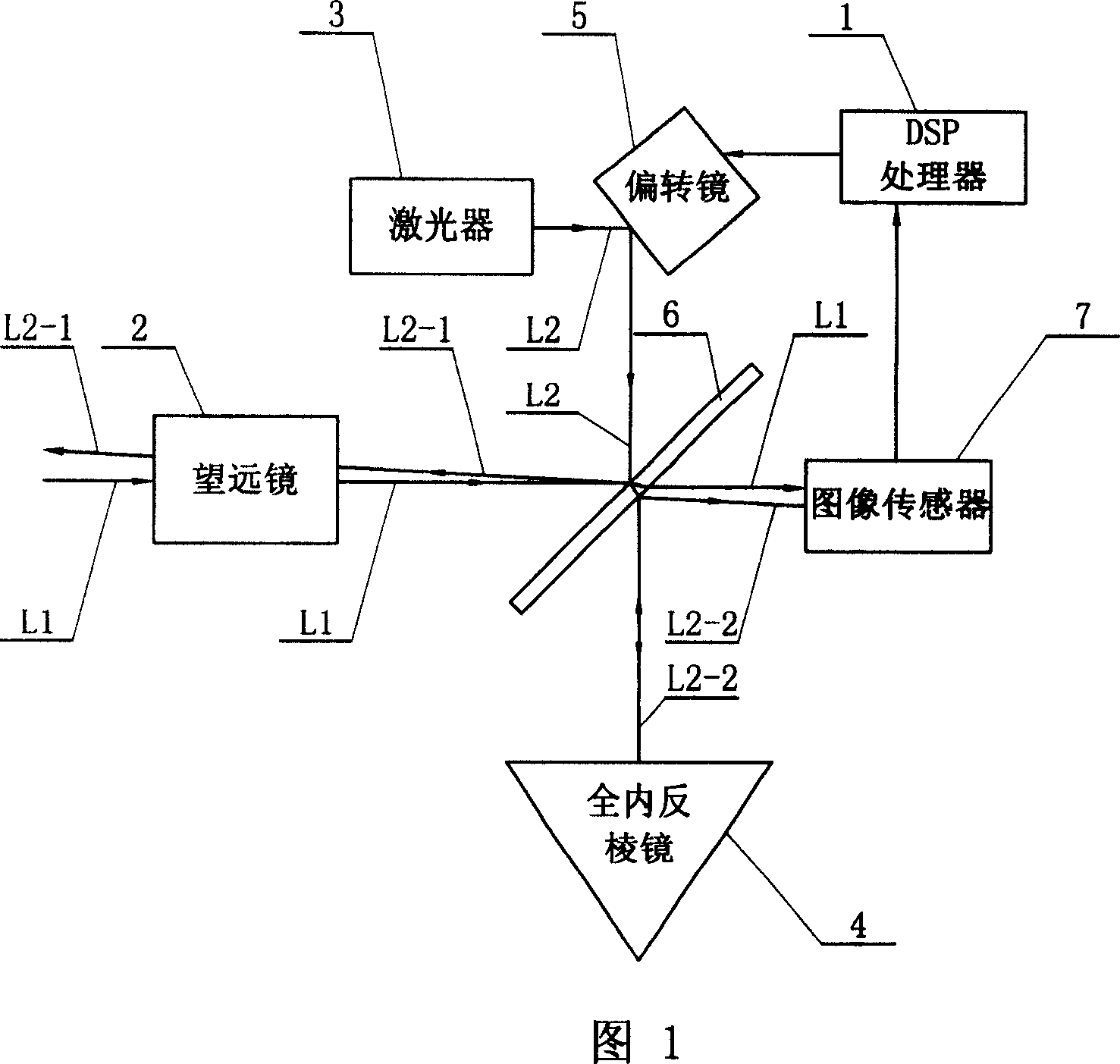
[0005] The present embodiment is described in conjunction with Fig. 1, and it is made up of DSP processor 1, telescope 2, laser device 3, total internal mirror 4, deflection mirror 5, beam splitter mirror 6, image sensor 7; Incident light beam L1 is input to the left end of telescope 2 , the light beam L1 is transmitted by the telescope 2 and output from the right end of the telescope 2 to the left end of the beam splitter 6, the light beam L1 passes through the beam splitter 6 and then enters the light input end of the image sensor 7; the laser beam L2 output by the laser 3 passes through The deflection mirror 5 is reflected to the left end of the beam splitter 6, and a part of the laser beam L2-1 is reflected to the right end of the telescope 2 through the beam splitter 6, and the laser beam L2-1 is transmitted through the telescope 2 and output from the left end of the telescope 2, Another part of the laser beam L2-2 passes through the beam splitter 6 and is reflected into t...


PUM


Abstract

A tracking and aiming device of light communication for satellite with transmit - receive and off - axis type applies transmit - receive and off - axis light path and one deflector as well as some other optical components to realize that received light signal is used to carry out tracking and aiming control of outgoing light beam. The device is small in volume and light in weight comparing with tracking and aiming device used in practice.

Description

Technical field: [0001] The invention relates to the technical field of satellite optical communication tracking and aiming devices. Background technique: [0002] In satellite optical communication, the tracking and aiming device is required to use the received optical signal to track the outgoing beam and control the aiming. Due to the long distance of communication and the high relative speed of the terminal, it is necessary to consider the tracking and aiming control error caused by the beam transmission delay. Considering that the orbital positions of the two link satellites can be predicted, an advance aiming device is usually set in the optical communication terminal to compensate for the advance aiming angle. In the receiving and transmitting optical paths of existing devices (such as the SILEX system of the European Space Agency), the coaxial transmission and reception method is mostly used: that is, the ideal beam tracking angle coincides with the receiving optica...

Claims


Application Information

Patent Timeline
Patent Type & Authority Patents(China)
IPC IPC(8): G02B26/08G01C21/00
Inventor 马晶谭立英于思源韩琦琦陈云亮
Owner HARBIN INST OF TECH
Learn More