
Process of making a hollow member having an internal coating and turbine components

A technology of inner coating and hollow casting, which is applied in the field of manufacturing a hollow casting component, and can solve the problem that the spraying process cannot be satisfactorily applied

Inactive Publication Date: 2007-05-30
SIEMENS AG
View PDF4 Cites 0 Cited by
  • Summary
  • Abstract
  • Description
  • Claims
  • Application Information

AI Technical Summary

Problems solved by technology

The spray process cannot be satisfactorily applied to spray coat the interior walls of hollow castings

Method used


Image

  • Process of making a hollow member having an internal coating and turbine components
  • Process of making a hollow member having an internal coating and turbine components

Examples


Embodiment Construction

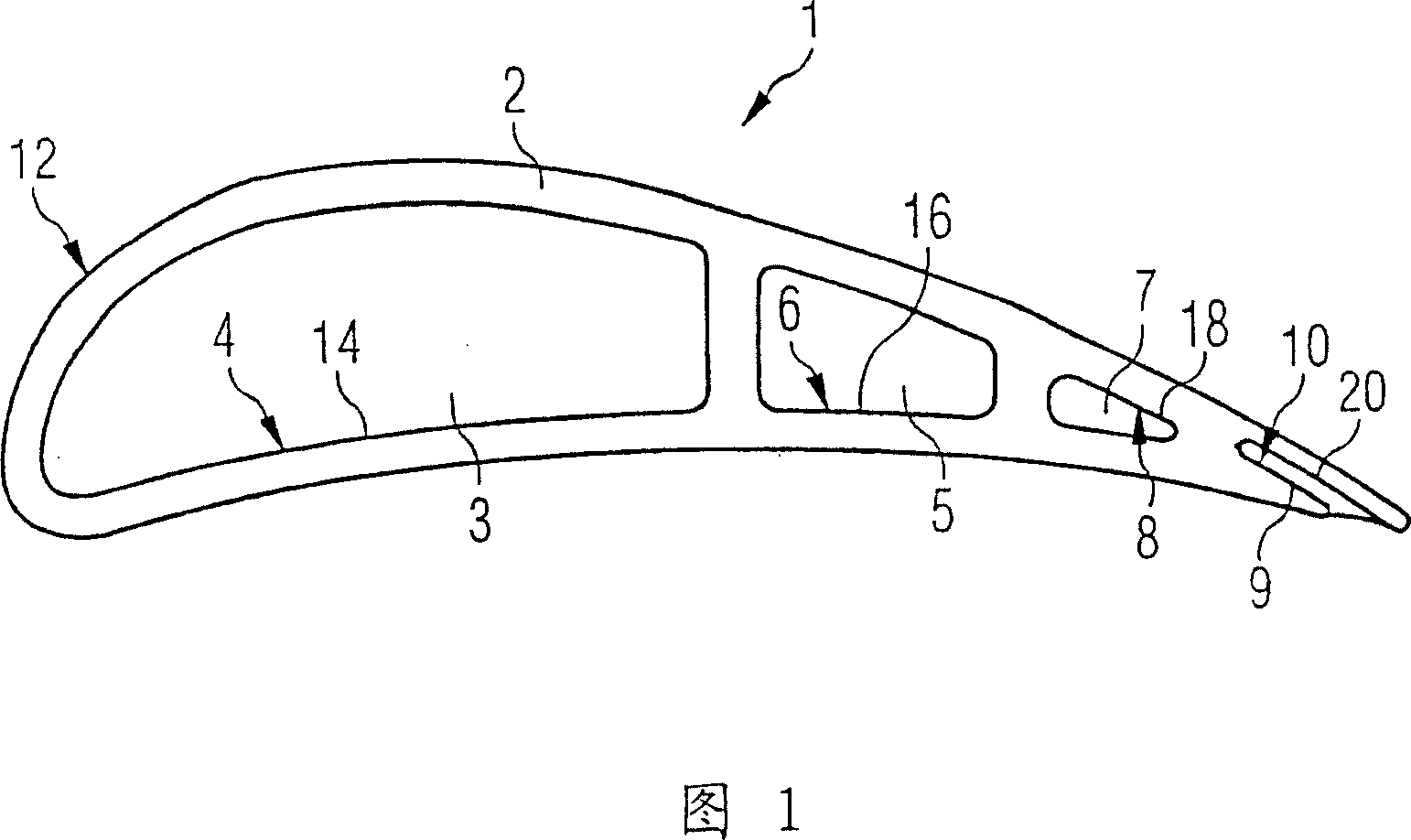
[0020] FIG. 1 is a schematic sectional view of a hollow cast turbine blade 1 . The turbine blade 1 includes a blade body 2 . In the exemplary embodiment shown, four cavities 3 , 5 , 7 , 9 are formed in the blade body 2 . These cavities are used, for example, for cooling air to flow through. The blade body 2 has an outer surface 12 . The outer surface is protected against oxidation and / or corrosion with a MCrAlY coating. In addition, the blade body 2 also has inner surfaces 4 , 6 , 8 , 10 . These inner surfaces define cavities 3, 5, 7, 9 and form the inner walls of these cavities. These inner surfaces 4, 6, 8, 10 are likewise provided with an MCrAlY coating 14, 16, 18, 20 to protect against corrosion and / or oxidation.

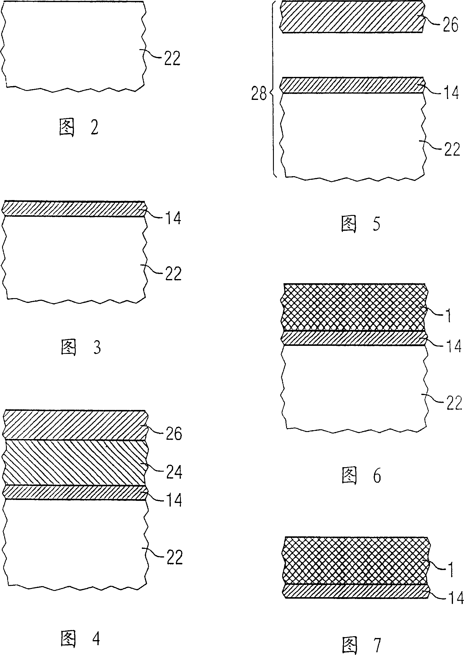
[0021] The method for producing the turbine blade 1 shown in FIG. 1 is described below with reference to FIGS. 2 to 7 . However, the method can also be used for internal coating of other hollow cast components.

[0022] As a first step, a ceramic casting ...


PUM

PropertyMeasurementUnit
melting pointaaaaaaaaaa

Abstract

A hollow cast turbine component is produced by: - (i) providing a cast mold comprising a mold insert defining at least one cavity to cast a component; applying a coating material to the portion of the cast mold that defines the cavity; - (ii) casting the component from a base material using the cast mold; and - (iii) removing the mold insert from the cavity of the component after the casting.

Description

technical field [0001] The invention relates to a method for producing a hollow cast component, in particular a hollow cast turbine component, the inner wall of at least one cavity of which is provided with an inner coating. Background technique [0002] Components exposed to high thermal loads can have a coating on their outer sides in order to protect them from corrosion and / or oxidation in thermally loaded areas. MCrAlY coatings are particularly suitable for this purpose. A MCrAlY coating can be understood within the scope of this specification as a metal alloy coating comprising chromium (Cr) and aluminum (Al), where Y represents yttrium or a rare earth element, M represents iron (Fe ), cobalt (Co) or nickel (Ni). [0003] However, under certain working conditions, the inner wall of the hollow casting working in the high thermal load area will also bear high temperature, so it is also necessary to prevent the inner wall from being corroded and / or oxidized, so that the ...

Claims


Application Information

Patent Timeline
Patent Type & Authority Patents(China)
IPC IPC(8): B22C9/10B22C9/24B22D25/00B22C1/00B22C3/00B22C7/02B22C9/00B22C9/04B22C9/12B32B15/00F01D5/18
CPCB22D27/15B22C9/12B22C9/04F01D5/18B22C1/165F05D2230/90F01D5/288B22D29/002B22C7/02F05B2230/90
Inventor 克努特·哈伯斯塔特
Owner SIEMENS AG
Learn More