Completion system of oil and gas wells with regulatably controlling flows of formation fluid or filled fluid in divided sections

A technology for formation fluids and fluid flow, which is applied in the fields of production fluids, wellbore/well components, and earth-moving drilling, etc. It can solve the problems of difficult separation operation, complicated operation, and large operation workload, so as to reduce formation damage and simplify operation. Convenience and the effect of reducing completion costs

Inactive Publication Date: 2007-06-20
ANTON BAILIN OILFIELD TECH (BEIJING) CO LTD
View PDF3 Cites 1 Cited by
  • Summary
  • Abstract
  • Description
  • Claims
  • Application Information

AI Technical Summary

Problems solved by technology

[0011] 1. The number of layers sealed by the packer is limited. When there are more than four isolation areas to be separated, the separation operation is very difficult
[0012] 2. Due to the limited number of isolation areas sealed by packers, a single isolation area is relatively long. There may be oil, gas, and water producing layers in the same isolation area, and multi-phase fluids are mixed. The development of
[0013] 3. When it is necessary to adjust the isolation section, all the pipe strings must be taken out from the oil and gas well before the position of the packer can be adjusted. The workload is heavy and the operation is complicated
[0014] 4. In oil and gas wells with damaged or deformed casing, the packer cannot be used
[0015] 5. Due to the relatively long distance of the isolation section, the phenomenon of fluid layer channeling will occur between the different layers included in the same isolation section due to the difference in pressure, that is, the fluid in some layers flows into other layers, Therefore, it will affect the oil production
[0016] The above-mentioned shortcomings of oil and gas wells using packers restrict the further improvement of the economic benefits of oil and gas field development

Method used


Image

  • Completion system of oil and gas wells with regulatably controlling flows of formation fluid or filled fluid in divided sections
  • Completion system of oil and gas wells with regulatably controlling flows of formation fluid or filled fluid in divided sections
  • Completion system of oil and gas wells with regulatably controlling flows of formation fluid or filled fluid in divided sections

Examples


Embodiment 1

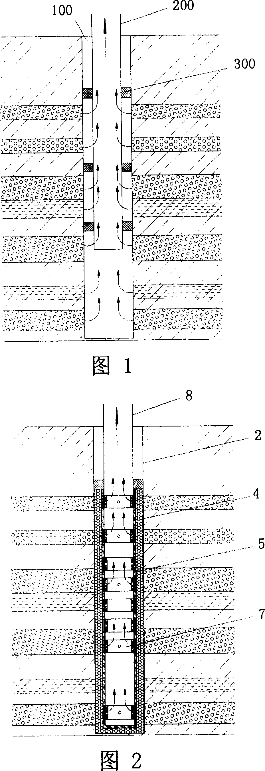
[0055] As shown in FIG. 2 , it is a schematic diagram of the overall structure of the oil and gas well completion system of the oil and gas well completion system for regulating the flow of formation fluid or injection fluid in subdivided sections according to the present invention. It can be seen from the figure that the system is at least composed of the flow regulating string 8 and the porous medium 4 arranged in the oil and gas well; Formation fluid or injection fluid flows axially along the oil and gas well in the annular space, while allowing formation fluid or injection fluid to seep radially along the oil and gas well. Its specific structure is shown in Figure 3. The flow regulating pipe string 8 is provided with a collecting hole 81 and a collecting cavity 9, and the collecting hole 81 is set The outside of the flow regulating string 8 is collected to its inside; or the injection fluid is dispersed from the inside of the flow regulating string 8 to its outside; the in...

Embodiment 2

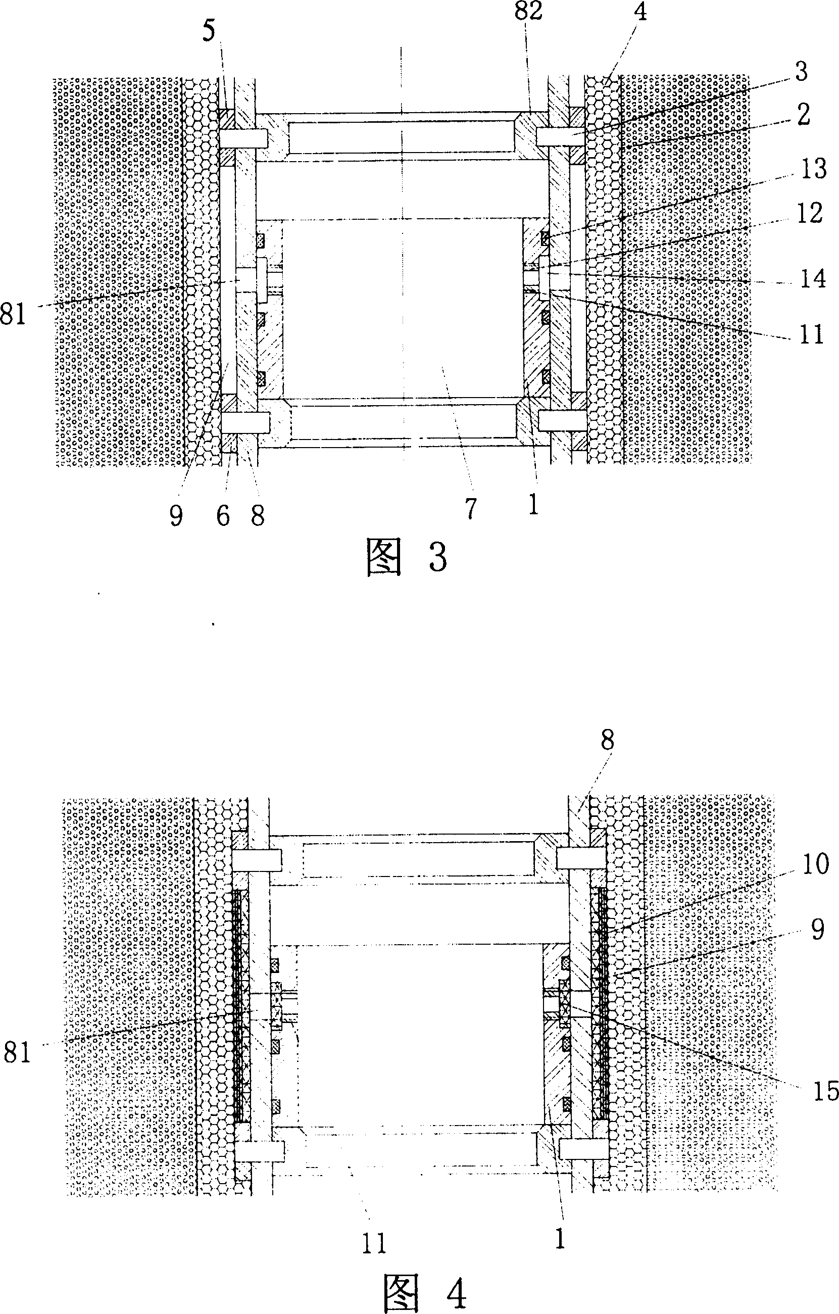
[0072] As shown in FIG. 4 , it is a schematic structural diagram of Embodiment 2 of the present invention. As can be seen from the figure, when the porous medium 4 is a loose porous medium (for example: formation sand, gravel particles, artificial granular medium), a sand control layer 10 is laid between the first upper isolation ring 5 and the second isolation ring 6, the The sand control layer 10 can be made of solid porous medium or metal mesh or metal fiber or wire-wrapped pipe or slotted pipe; The collecting cavity 9 is covered with a sand control layer 10, and the collecting hole 81 located on the flow regulating pipe string 8 communicates with the collecting cavity 9. Flow cavity 9, and flow into the flow cavity 9 through the manifold hole 81.

[0073] Referring to Fig. 4, on the inner side of the collecting pipe string 8, a sliding sleeve 1 that can slide along the axial direction of the oil and gas well is provided at the position corresponding to the collecting hole...

Embodiment 3

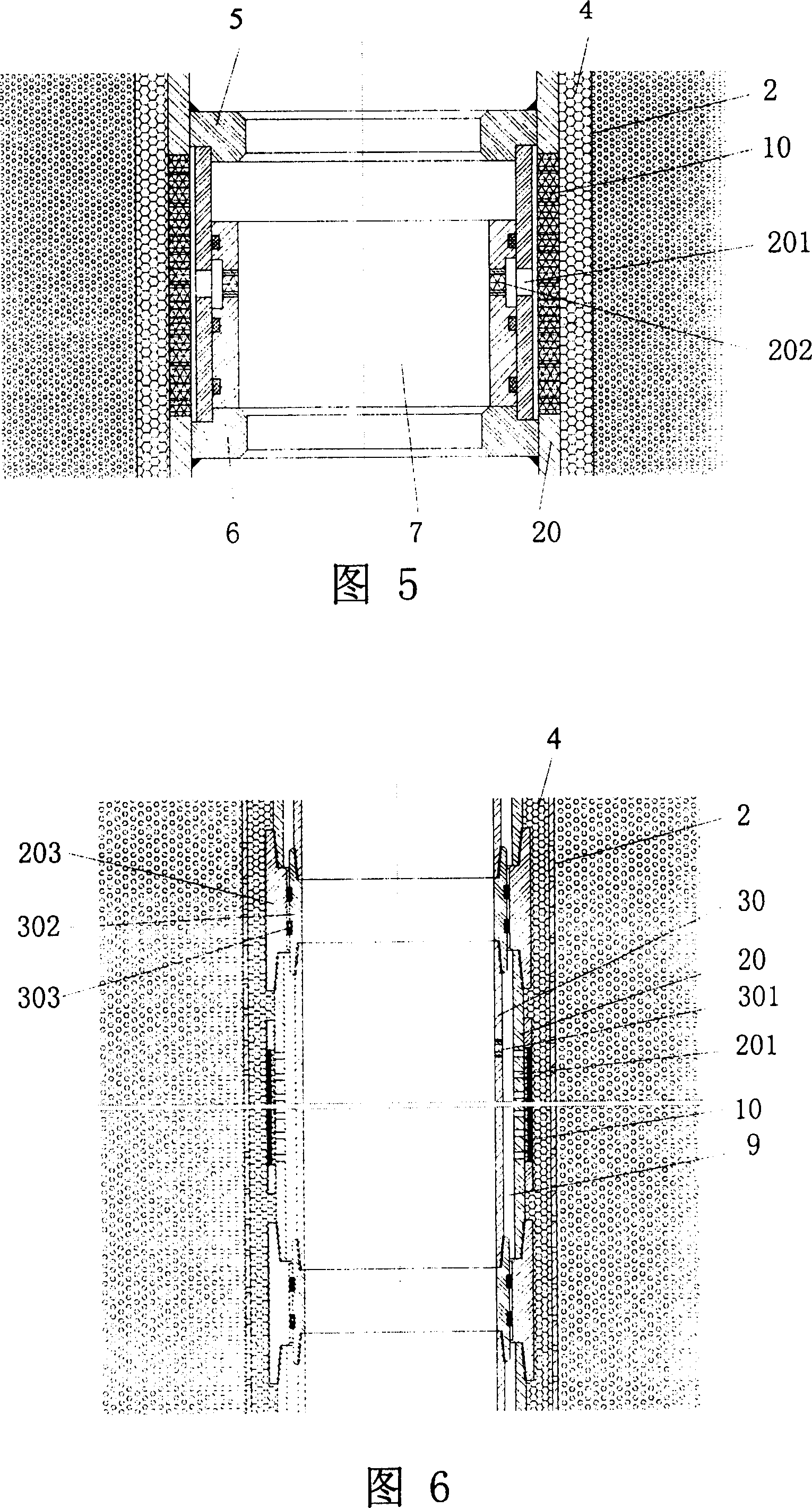
[0077] As shown in FIG. 5 , it is a schematic structural diagram of Embodiment 3 of the present invention. It can be seen from the figure that the system is at least composed of a screen 20 and a porous medium 4 arranged in the oil and gas well; The space flows along the axial direction of the oil and gas well, and at the same time allows the formation fluid or injection fluid to flow radially along the oil and gas well; The outer side is collected to its inner side, or the injection fluid is dispersed from the inner side of the screen pipe 20 to its outer side; the flow control device 7 is provided at the collecting hole 201 inside the screen pipe 20, which is used to control formation fluid or injection fluid from the The manifold 201 flows in or out.

[0078]The screen pipe 20 can be divided into more than one isolation unit by the first and second isolation rings 5, 6, and there are more than two isolation rings 5, 6, and at least one flow control device 7 is arranged in ...


PUM


Abstract

A finished oil (or gas) well system able to segmentally control the stratum fluid or injected fluid is at least composed of the fluid regulating pipe in the well and the porous medium in the gap between said regulating pipe and well wall. Said fluid regulating pipe has fluid collecting holes, fluid collecting cavities and the flow controllers relative to said fluid collecting holes for regulating the flow of stratum fluid or injected fluid flowing through said fluid collecting hole. It is suitable for the multi-layer oil deposit to pack multiple segments.

Description

Technical field: [0001] The invention relates to an oil and gas well completion system for subdividing sections to regulate the flow of formation fluid or injection fluid, especially an oil and gas well suitable for application in heterogeneous and multi-production layer oil reservoirs. The fluid flow rate inside it is The invention is controllable and belongs to the technical field of oil exploitation. Background technique: [0002] Many oilfields have heterogeneous, multi-layered sandstone reservoirs with large interlayer, plane, and intralayer variability. In particular, there are large differences in permeability between layers, and these differences have a great impact on the development effect of the reservoir. Different development strata need to be distinguished during the mining process. Each well needs to be exploited in several or more than a dozen sub-layers. For this kind of multi-yield reservoir, during the development process, it is necessary to control the ...

Claims


Application Information

Patent Timeline
Patent Type & Authority Patents(China)
IPC IPC(8): E21B43/14E21B43/12
Inventor 黄春宏陈继初
Owner ANTON BAILIN OILFIELD TECH (BEIJING) CO LTD
Why Eureka
Try Eureka