
Device and method for preheating combustibles in combined gas and turbine installations

A steam turbine and combined technology, which is applied in the direction of steam engine devices, mechanical equipment, turbine/propellant fuel delivery systems, etc., can solve the problems of high processing and maintenance costs, rarely achieved, sensitive to temperature changes of fuel preheaters, etc.

Inactive Publication Date: 2007-07-11
SIEMENS AG
View PDF6 Cites 0 Cited by
  • Summary
  • Abstract
  • Description
  • Claims
  • Application Information

AI Technical Summary

Problems solved by technology

[0003] The disadvantage of the solution described above is that the fuel preheater has to be designed with a high pressure, which makes the fuel preheater rather sensitive to temperature changes and is expensive in manufacturing and maintenance
Furthermore, even in modern gas turbines, the fuel itself is rarely preheated to 200° C., since preheating at higher temperatures creates problems such as so-called "combustion chamber noise", so it is currently hardly possible to install such expensive preheating system

Method used


Image

  • Device and method for preheating combustibles in combined gas and turbine installations
  • Device and method for preheating combustibles in combined gas and turbine installations
  • Device and method for preheating combustibles in combined gas and turbine installations

Examples


Embodiment Construction

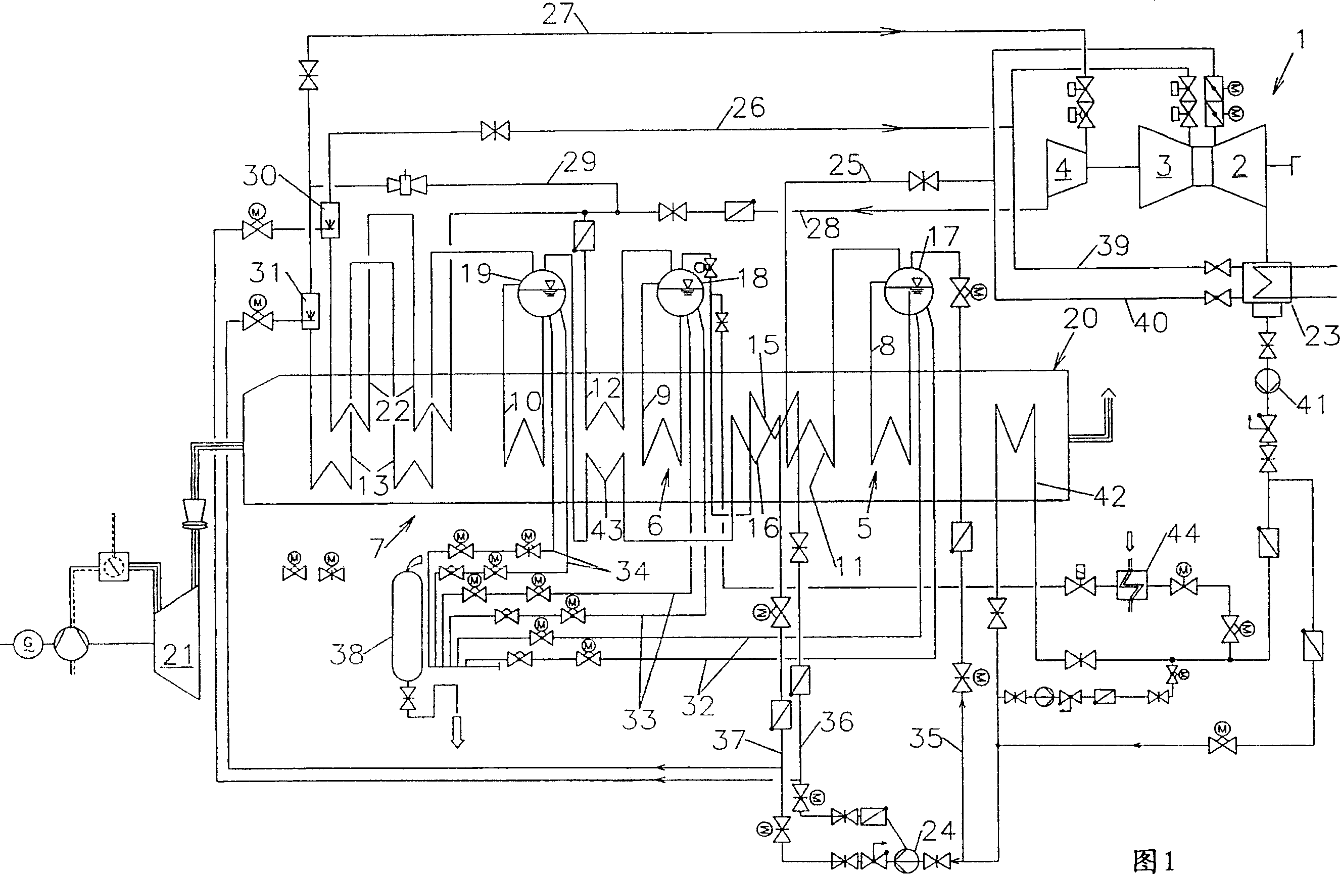
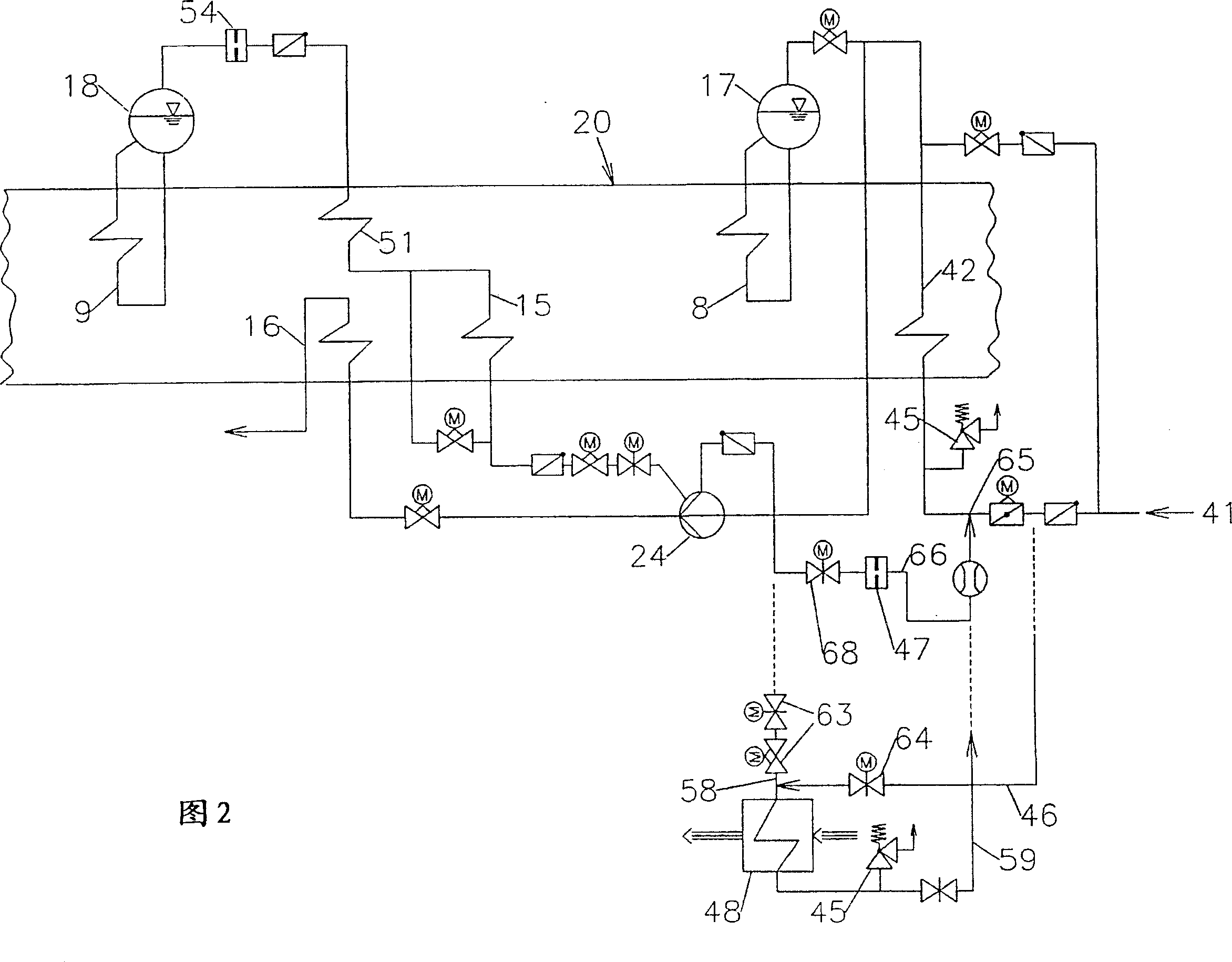
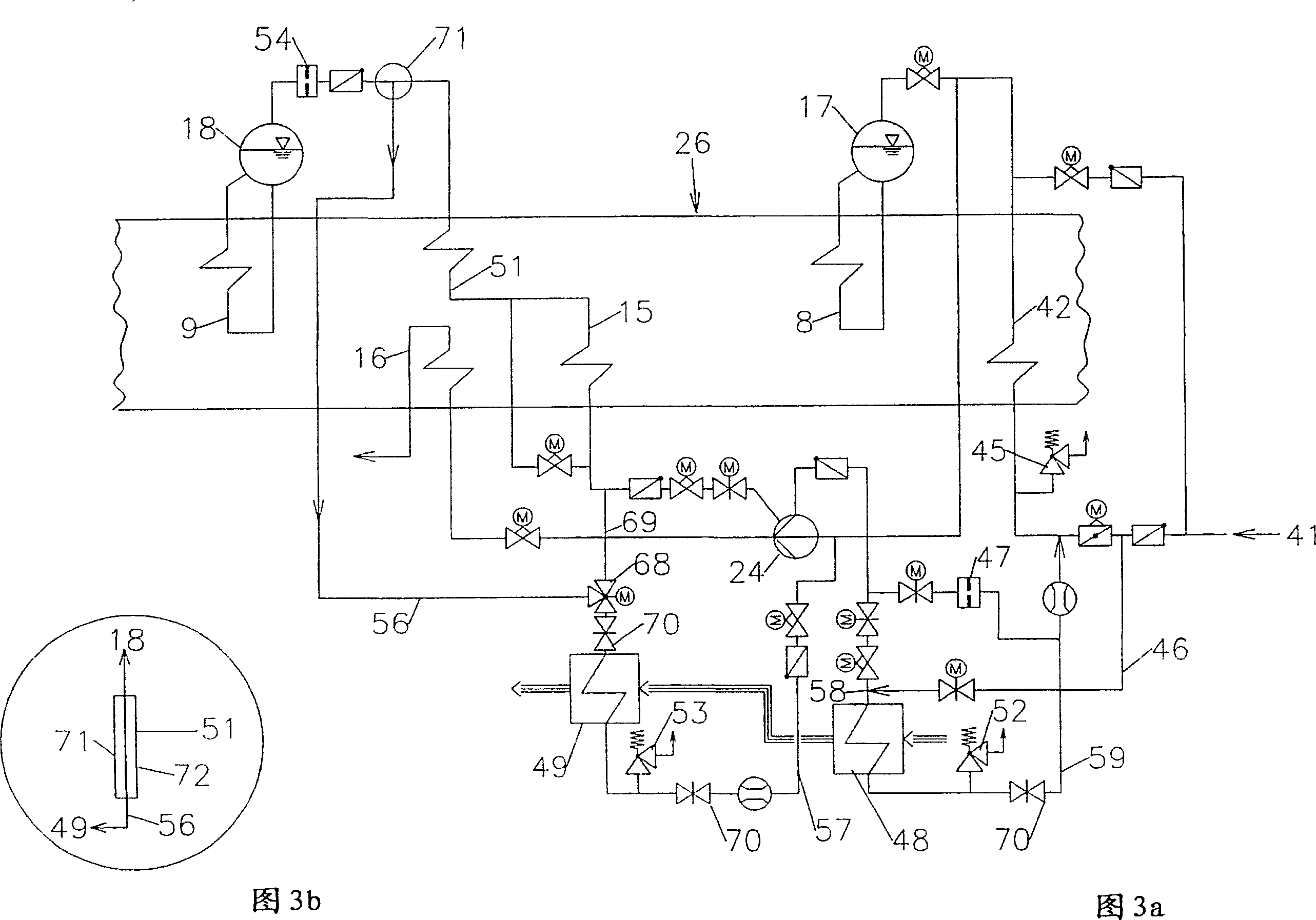
[0029] FIG. 1 shows a gas and steam turbine plant in schematic form. The steam turbine unit 1 consists of three turbine stages 2 , 3 , 4 , namely a low-pressure steam stage 2 , a medium-pressure steam stage 3 and a high-pressure steam stage 4 . The turbine stages 2 , 3 , 4 are each supplied with steam via three steam generators 5 , 6 , 7 , namely a low-pressure steam generator 5 , a medium-pressure steam generator 6 and a high-pressure steam generator 7 .

[0030]The steam generators 5, 6, 7 are of similar construction in principle. These steam generators 5,6,7 are respectively composed of an evaporator 8,9,10, a superheater 11,12,13, a condensation preheater 42 or a feed water preheater 15,16 and a steam drum 17, 18 , 19 , and a heat source 20 , in which feedwater condensate and feedwater steam are collected in a steam drum, which heat source 20 is supplied by the exhaust gas of a gas turbine 21 in the illustrated case.

[0031] The feed water is first preheated in a conden...


PUM


Abstract

The combined gas / steam turbine assembly has at least one steam generator to heat, evaporate and superheat the water supply. It has a water preheating stage (15,16), an evaporator (8,9) and a superheater. To preheat the fuel supply, a water supply channel is fed with water at a given temperature and, after raising the fuel temperature, the cooled water is returned through an outflow channel. The fuel is heated in separate and successive heating stages (48,49), with individual switching for the turbines. The fuel heating stages have a condensation heater (42) in the system.

Description

technical field [0001] The invention relates to a device for preheating fuel in a combined gas and steam turbine plant with at least one steam generator for heating, evaporating and superheating feed water, the generator having a feed water preheater or A condensate preheater, an evaporator and a superheater, wherein at least a portion of the heated feedwater can be used to preheat the fuel and the fuel preheater can be supplied with a given temperature via a feedwater inlet line Feed water, which is cooled after preheating the fuel, is discharged via a feed water discharge pipe. Background technique [0002] As disclosed in European patent application EP0931911A, in order to provide steam to drive a steam turbine, feed water is heated, evaporated and superheated at high pressure. This is usually done in several steam generator stages, ie in a low-pressure steam generator stage, a medium-pressure steam generator stage and a high-pressure steam generator stage. The steam ge...

Claims


Application Information

Patent Timeline
Patent Type & Authority Patents(China)
IPC IPC(8): F01K23/10F02C7/224
CPCF05D2220/74Y02E20/18F01K23/106F05D2220/72F02C7/224
Inventor 埃里克·施密德迈克尔·肖特勒
Owner SIEMENS AG
Learn More