Gas dissolving device

A technology of dissolving device and gas, applied in the directions of dissolving, dissolving, transportation and packaging, can solve the problems of high water discharge, increased manufacturing cost, and reduced oxygen dissolved amount, etc., to reduce manufacturing cost, reduce maintenance cost, and increase contact area. Effect

Inactive Publication Date: 2007-07-18
DAE YOUNG +1
View PDF8 Cites 1 Cited by
  • Summary
  • Abstract
  • Description
  • Claims
  • Application Information

AI Technical Summary

Problems solved by technology

[0018] However, due to the above-mentioned existing oxygen dissolving device 100, its structural characteristics make water drop from each through hole 106a, 107a of the diffusion plate 106, 107 to form a droplet (water drop). The flow rate of the liquid is limited to an extremely small value through the holes 106a and 107a, so there is a problem that the treatment capacity is low (the amount of oxygen-dissolved water discharged from the container 102 is small).
[0019] And, when between the above-mentioned diffuser plate 106 and the diffuser plate 107, or between the diffuser plate 107 and the top surface of the container 102, when the water restricted by the diffuser plates 106, 107 is filled, since the diffuser plates 106, 107 cannot be more Oxygen supply to the space below will lead to a decrease in the oxygen concentration in the space, resulting in a decrease in the amount of dissolved oxygen in the water
In particular, since the above-mentioned industrial drainage or domestic drainage contains foreign matter such as garbage, the foreign matter tends to clog the through-holes 106a, 107a of the diffusion plates 106, 107, and the above-mentioned problems tend to occur.
[0020] And, when the through-holes 106a, 107a are blocked by foreign matter, it is necessary to disassemble the container 102 to remove the blocked foreign matter. For this reason, the maintenance cost of the device will be increased. If the container 102 is made into a detachable structure, To meet the needs of removing foreign matter, the structure tends to be complicated, the manufacturing cost increases, and the airtightness of the container 102 is insufficient.
[0021] In addition, since the inner diameters of the water supply pipe 104b and the drain pipe 105 are approximately equal, although the water supply volume and the discharge volume can be approximately equal, when the oxygen pressure in the container 102 rises for some reason, the discharge volume is likely to be greater than the water supply volume. amount, the problem of reducing the amount of water stored in the container 102
[0022] In addition, when it is detected by the water level detector 108 that the water level in the container 102 has dropped to exceed the lower limit, although the water discharge can be adjusted by adjusting the opening of the supply valve 103c, it may take some time for the water level to recover, so sometimes the water level drops to Under the opening of the drain pipe 105, the oxygen in the container 102 leaks from the drain pipe 105 to the outside

Method used


Image

  • Gas dissolving device
  • Gas dissolving device
  • Gas dissolving device

Examples


Embodiment approach 1

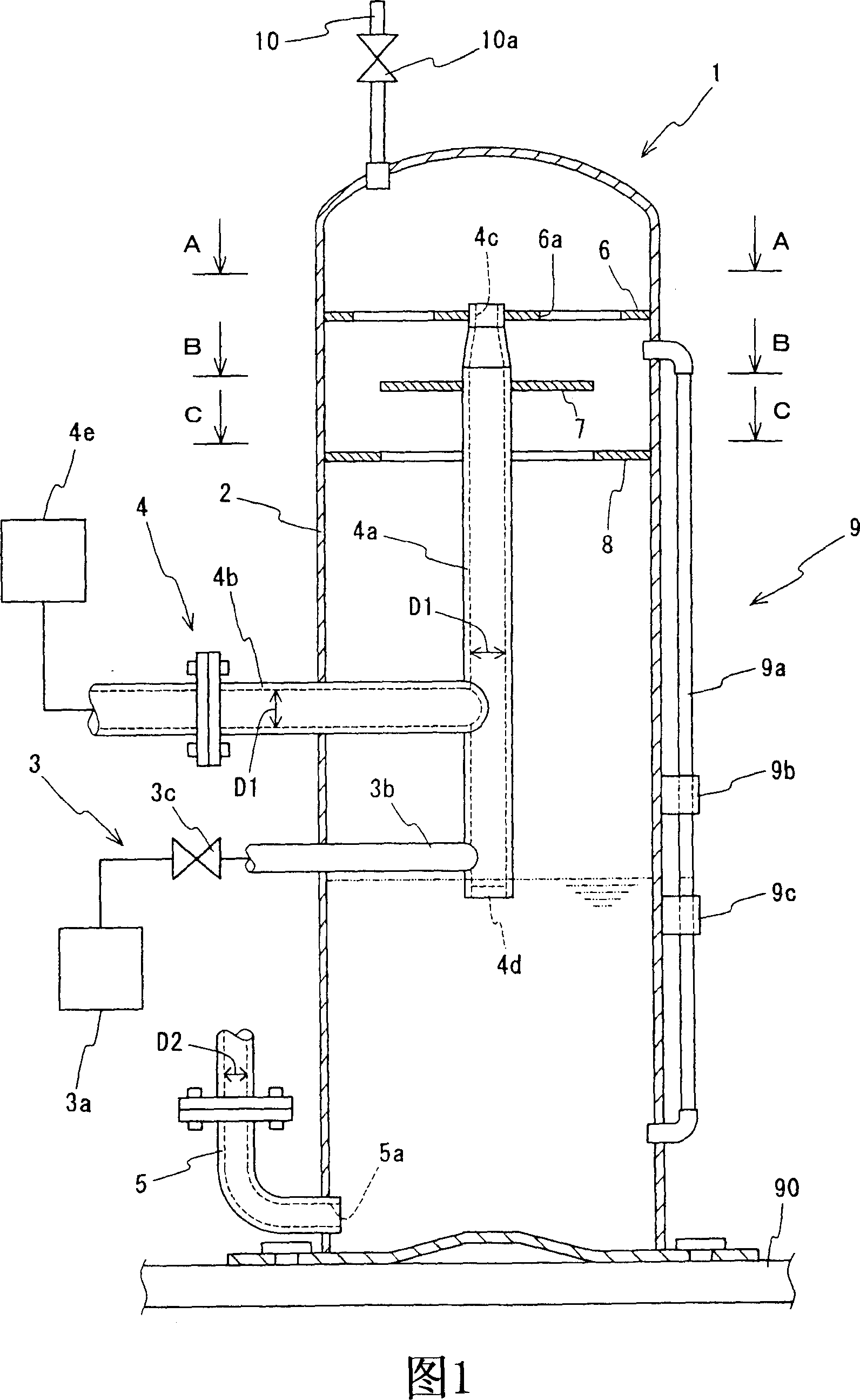
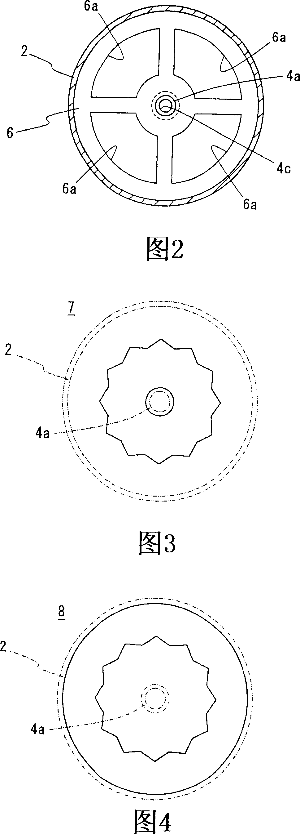
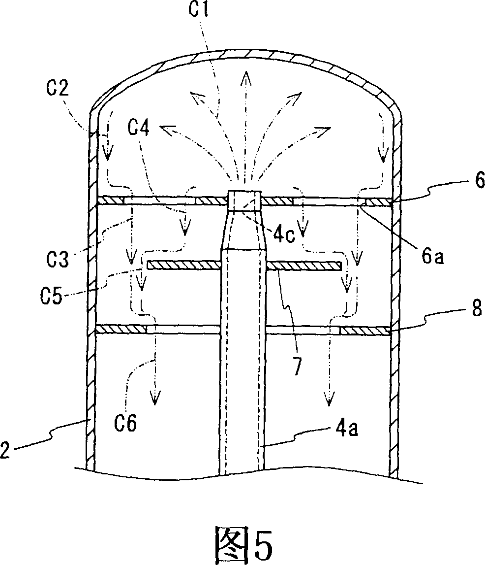
[0050] First, Embodiment 1 of the present invention will be described with reference to FIGS. 1 to 5 . Wherein, Fig. 1 is a sectional view of the brief structure of the oxygen dissolving device according to Embodiment 1 of the present invention; Fig. 2 is a sectional view along the arrow A-A direction in Fig. 1; Fig. 3 is a sectional view along the arrow B-B direction in Fig. 1; Fig. 4 is a cross-sectional view along the arrow C-C direction in FIG. 1; FIG. 5 is a schematic diagram of water flow in Embodiment 1.

[0051] As shown in FIGS. 1 to 4 , the oxygen dissolving device 1 of the present embodiment includes: a container 2 with a closed space; an oxygen supply mechanism 3 for supplying oxygen in the container 2; a pressure detector ( not shown in the figure); the water supply mechanism 4 for supplying water in the container 2; the drain pipe 5 for discharging the water inside the container 2; , 8; and a water level detector 9 that detects the water level in the container 2...

Embodiment approach 2

[0102] Next, Embodiment 2 of the present invention will be described with reference to FIGS. 6 to 8 . Fig. 6 is a cross-sectional view of the brief structure of the oxygen dissolving device according to Embodiment 2 of the present invention; Fig. 7 is a cross-sectional view along the arrow D-D direction in Fig. 1; Fig. 8 is a schematic diagram of water flow in Embodiment 2.

[0103] As shown in Figure 6, in the present embodiment, the oxygen dissolving device 20 has the oxygen supply mechanism 3, the water supply mechanism 4, the drain pipe 5 and the restrictor plates 6, 7, 8 in the oxygen dissolving device 1 of the above-mentioned embodiment 1. different, but the same structural parts as the oxygen dissolving device 1 are marked with the same symbols, and the detailed description thereof will be omitted.

[0104] As shown in Fig. 6 and Fig. 7, the oxygen dissolving device 20 of the present embodiment has: the above-mentioned container 2; an oxygen supply mechanism 21 for supp...


PUM


Abstract

The invention relates to a gas dissolving device having high processing power and capable of efficiently dissolving gas in water. A gas dissolving device (1) comprises a vessel body (2) having a sealed space, a gas supplying mechanism (3) provided with a supply tube (3b) connected to the vessel body (2), so as to supply a gas to the vessel body (2) through the supply tube (3b) until the gas pressure in the vessel body (2) is increased to the atmospheric pressure or above, a water supply mechanism (4) provided with water supply tubes (4a, 4b) connected to the vessel body (2), so as to supply water to the vessel body (2) through the water supply tubes (4a, 4b), and a drain tube (5) for discharging the gas-dissolved water stored in the bottom of the vessel body (2) to the outside, the arrangement being such that gas is dissolved in water by bringing gas and water into gas-liquid contact in the vessel body (2). The water supply tube (4a) is vertically disposed in the vessel body (2) and is provided with a delivery port (4c) which opens to the upper end surface, the arrangement being such that water is delivered from the delivery port (4c) upwardly toward the ceiling of the vessel body (2). The water supply tube (3b) is connected to the water supply tube (4a) to supply a gas to the vessel body (2) through the water supply tube (4a).

Description

technical field [0001] The present invention relates to a gas dissolving device for dissolving gas in water. Background technique [0002] In waters such as lakes, rivers, etc., there are industrial wastewater discharged from various facilities such as construction sites or offices built around them or domestic wastewater discharged from ordinary households. Because these discharged wastewater contains phosphorus compounds and nitrogen compounds, etc. organic matter, thus causing water pollution problems in which the waters are polluted. [0003] In recent years, there has been a method of improving the quality of polluted water by removing or reducing excess organic matter from polluted water (water to be purified) using microorganisms capable of decomposing organic matter. Specifically, oxygen is supplied to microorganisms (aerobic microorganisms) in the water to be purified to activate the microorganisms. By activating the microorganisms, the decomposition of organic mat...

Claims


Application Information

Patent Timeline
Patent Type & Authority Patents(China)
IPC IPC(8): B01F1/00C02F3/22B01F25/70
CPCB01F5/18B01F3/04496B01F23/2322B01F25/70C02F3/02C02F2103/007C02F2301/06C02F2209/42
Inventor 森田通夫奥田正明
Owner DAE YOUNG
Why Eureka
Try Eureka