
Air-supplying motor equipment for drying machine

A technology for blowing motors and fixing devices, which is applied in the direction of electromechanical devices, pump devices, machines/engines, etc., and can solve problems such as insufficient rotation frequency, reduced air supply capacity, and weak strength, so as to ensure strength and prevent air supply capacity Falling effect

Inactive Publication Date: 2007-08-01
LG ELECTRONICS (TIANJIN) APPLIANCES CO LTD
View PDF3 Cites 1 Cited by
  • Summary
  • Abstract
  • Description
  • Claims
  • Application Information

AI Technical Summary

Problems solved by technology

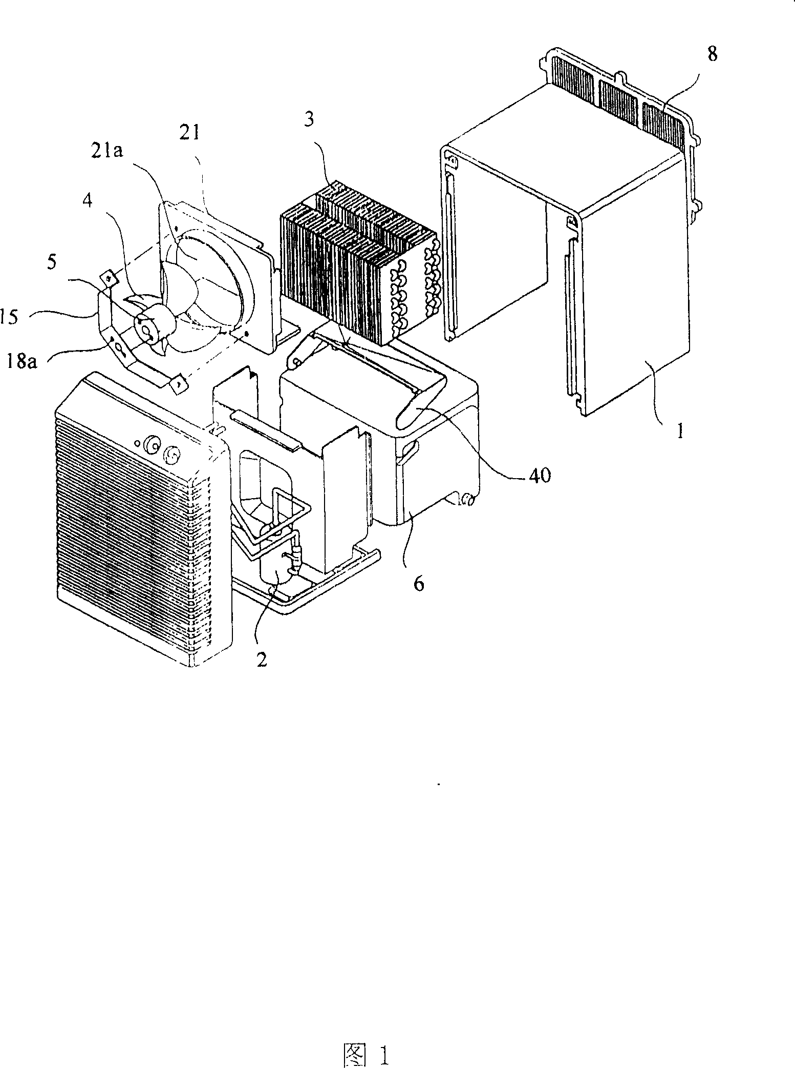
[0009] However, the strength of the motor support 15 seen above is weak. If the structure is deformed, the air supply capacity will be significantly reduced due to the insufficient rotation frequency of the fan 4 at the fan hole, and of course there will be serious noise. question

Method used


Image

  • Air-supplying motor equipment for drying machine
  • Air-supplying motor equipment for drying machine
  • Air-supplying motor equipment for drying machine

Examples


Embodiment Construction

[0031] The present invention is described in further detail in conjunction with accompanying drawing and embodiment:

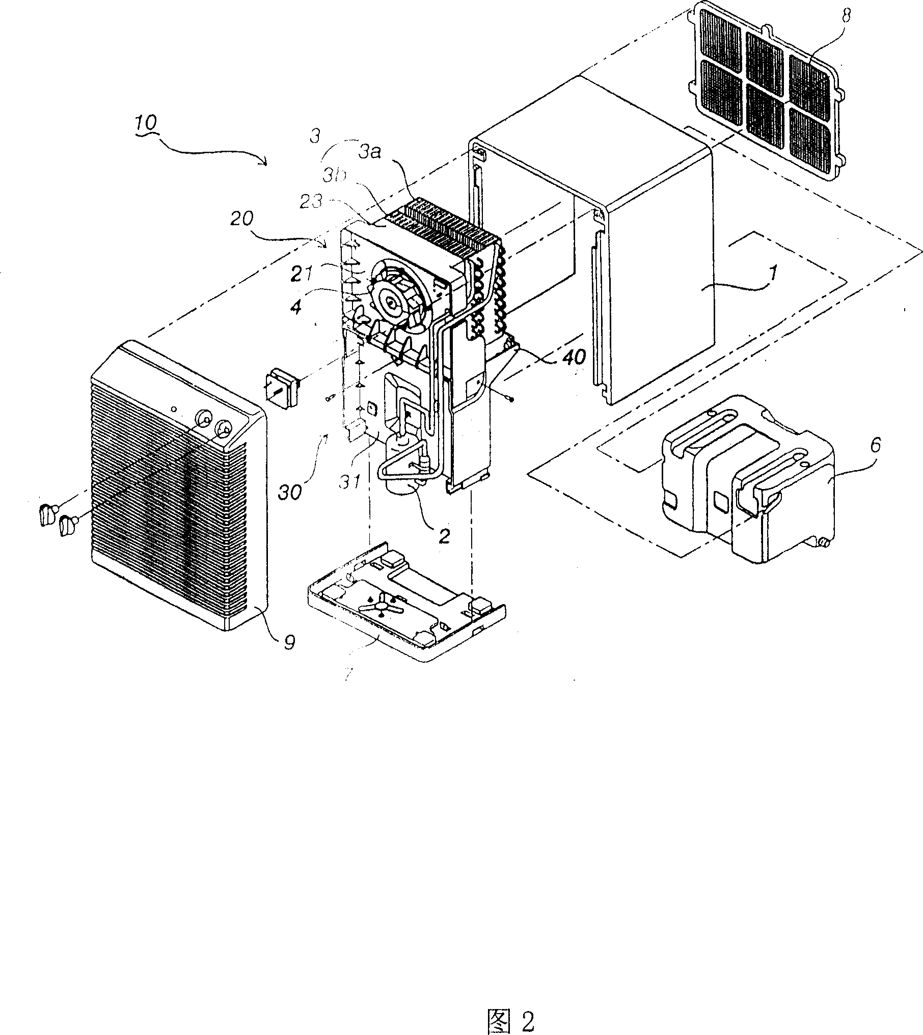
[0032] As shown in Figure 2, the drying machine of the present invention has a casing in which various devices can be installed, the casing is connected to the chassis at its lower part, and the side of the suction port on the back side of the casing is set as a filter that can purify the indoor air. In addition, the side of the air outlet at the front end is assembled into a guide grille.

[0033] Inside the casing 1, there is a compressor 2 that compresses and circulates the refrigerant, a heat exchanger 3 that uses an evaporator 3a and a condenser 3b to form indoor air heat exchange for dehumidification, and a heat exchanger located behind the heat exchanger 3. The fan 4 used to force the air flow, and the water tank 6 located on the lower side of the heat exchanger 3 to concentrate the condensed water, the above are the structures of various equipment insi...


PUM


Abstract

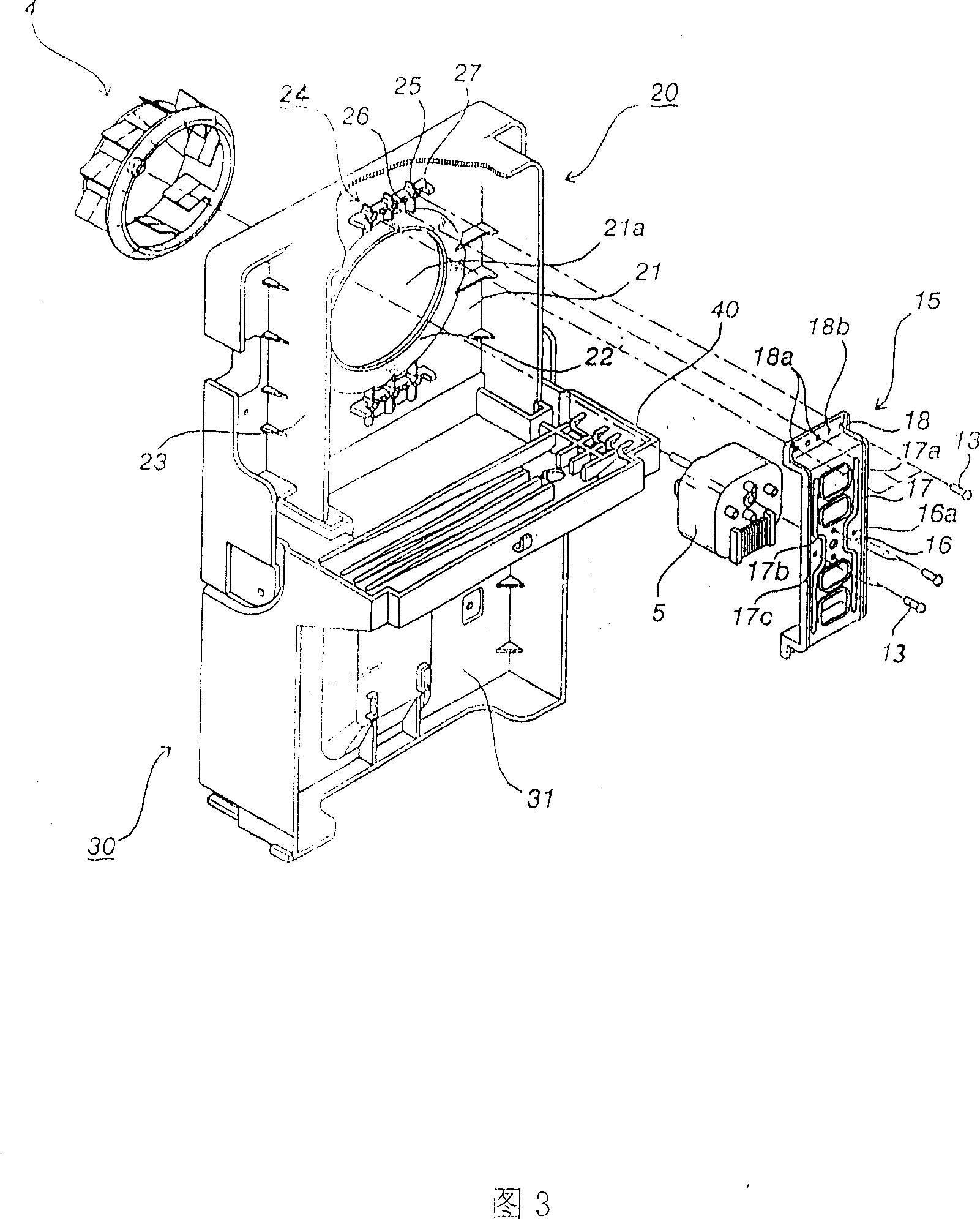
This invention relates to an air supply motor equipment of a drier. It makes an impeller inducer to stick to the hole inside of an aperture plate of a blower fan fixed panel, to fully maintain the support strength of the electrode support, aperture plate holes are designed on the panel. On which the motor is fixed by the electrode fixing support and more than one tenons and two supporting posts on its one end. On the motor frame tenous and screw holes are designed corresponding to those on the panel, tenous on which are inserted into the holes and the frame is fixed by screws and the support posts on the panel.

Description

technical field [0001] The invention relates to a dryer, in particular to a fixing device for a blower motor in the dryer. Background technique [0002] Prior art as shown in Figure 1, because the filter screen 8 of prior art drier is at the absorption mouth end of casing 1, the heat exchanger 3 that plays dehumidification effect is behind the filter screen 8, at the rear of heat exchanger 3 It is fan 4, so it can dehumidify through the forced flow of indoor air. [0003] Here, because the heat exchanger 3 is divided into an evaporator and a condenser, the working cycle refrigerant of the compressor 2 collects the water condensed from the condenser into the water tank 6 below. [0004] The fan fixing panel 21 is vertically fixed above the drainage groove 40, and the fan hole 21a of a predetermined size is for moving the airflow formed when the fan 4 works. [0005] In particular, the fan 4 is fixed by the motor 5 and the motor bracket 15 on the fan hole 21 a of a specified...

Claims


Application Information

Patent Timeline
Patent Type & Authority Patents(China)
IPC IPC(8): H02K5/00F04D25/08
Inventor 严南燮
Owner LG ELECTRONICS (TIANJIN) APPLIANCES CO LTD
Learn More