Computerized roentgenographing apparatus

A photography equipment, X-ray technology, used in X-ray equipment, computing, echo tomography, etc.

Inactive Publication Date: 2002-02-06
SIEMENS AG
View PDF0 Cites 15 Cited by
  • Summary
  • Abstract
  • Description
  • Claims
  • Application Information

AI Technical Summary

Problems solved by technology

Since it is not initially known to the extent to which soft tissue and bone tissue contribute to the radiation attenuation from the measurements obtained on examination of the patient, it is not possible to arrive at a satisfactory correction for radiation hardening based on known measurements alone

Method used


Image

  • Computerized roentgenographing apparatus
  • Computerized roentgenographing apparatus

Examples


Embodiment Construction

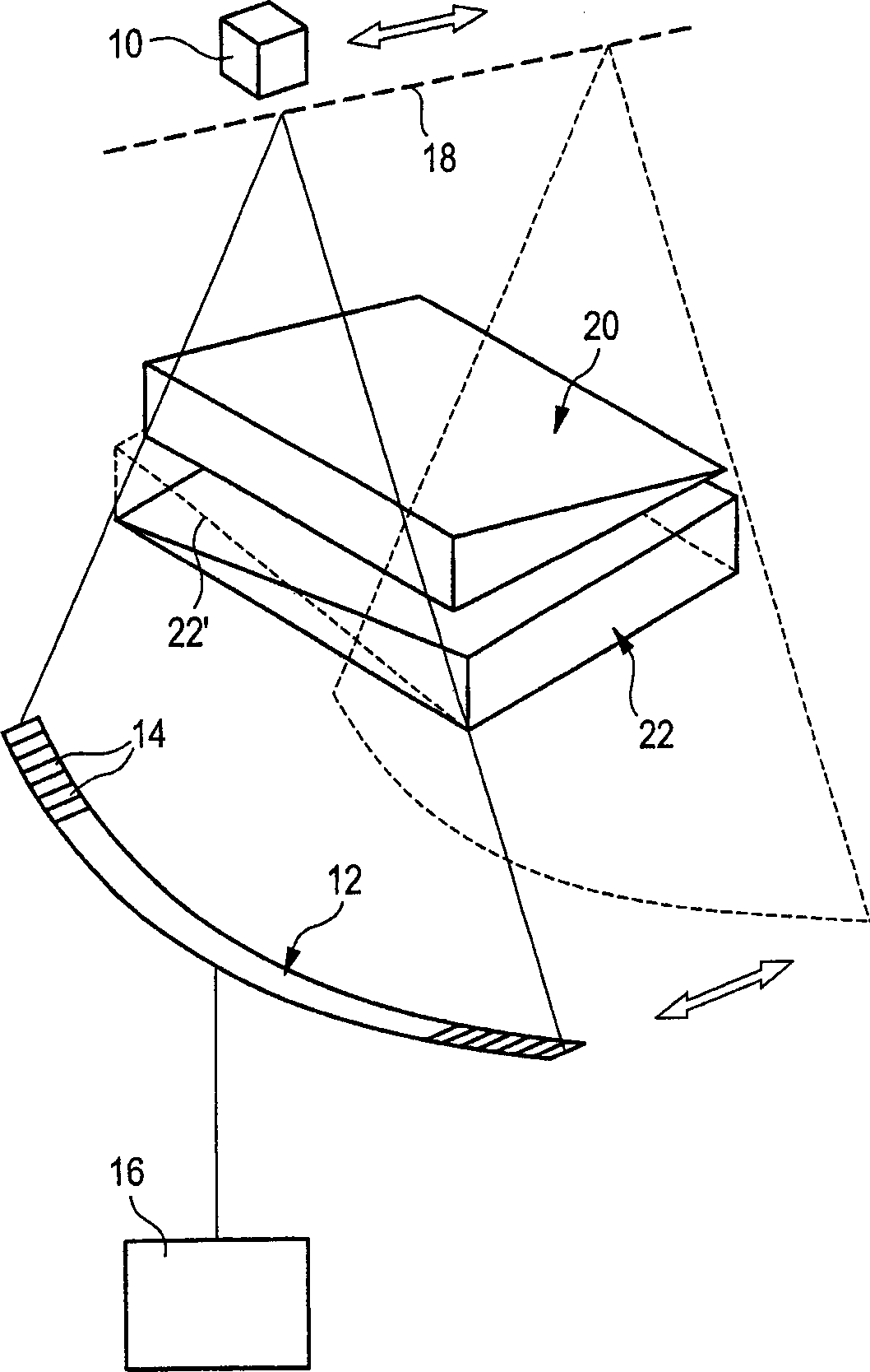
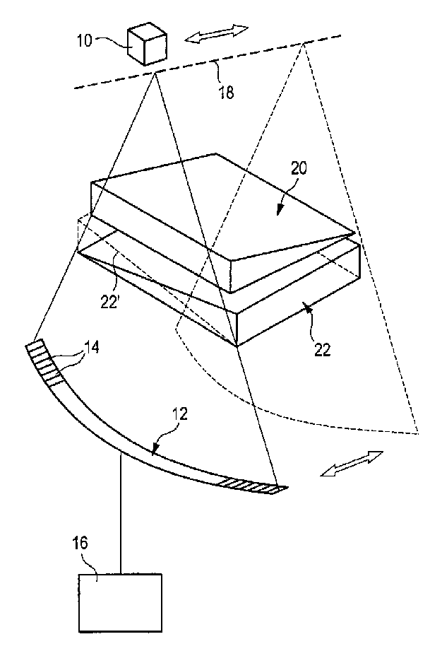
[0041] The total attenuation value of the reference can be determined by simulation on a computer or by measurement. Measurements can be made e.g. by attaching figure 1 Proceed as shown in . exist figure 1 A CT scanner can be seen in the figure, which comprises an x-ray radiation source 10 and a detection device 12 consisting of a plurality of detection elements 14 arranged side by side along a circular arc. The X-ray radiation source 10 emits X-rays fan-shaped in one plane. The detection elements 14 cover a total projection area extending along the angular range of the fan-shaped ray, wherein each detection element 14 detects the X-ray intensity incident in the projection subregion covered by it, and provides a corresponding intensity measurement signal Give an electronic calculation and reproduction unit 16 . The x-ray radiation source 10 and the detection device 12 are non-rotatably movable along an axis 18 perpendicular to the plane of the sector.

[0042] Within the ...


PUM


Abstract

In an X-ray computed tomography apparatus with retrospective beam hardening correction, an overall image of a body slice under examination is determined from overall attenuation values that are obtained from the body slice. At least one partial image that shows essentially only one body substance, such as bone substance, is extracted from this overall image. Attenuation partial values are employed for determining a correction value. The attenuation values are determined for each overall attenuation value from the at least one partial image by re-projection. A correction value is derived from the beam hardening error that is determined for a material combination of two different reference materials.

Description

technical field [0001] The invention relates to a radiation hardening correction in a computed tomography apparatus. Background technique [0002] In computed tomography, a shift of the mean energy of the x-rays to greater values ​​occurs due to the multichromatic nature of the radiation emitted by the x-ray source and to the energy-dependent absorption of the x-rays in the body of the patient under examination. This effect is called ray hardening (Strahlaufhaertung). This effect is stronger the longer the path of transmission in the body. This radiation hardening effect leads to undesired image distortions in the reconstructed image of the transmitted tomography, which distortions impede a medically accurate interpretation of this image. [0003] To correct such image distortions due to radiation hardening, standard algorithms are known (e.g. so-called polynomial corrections) which lead to satisfactory results, e.g. as long as the spectral absorption...

Claims


Application Information

Patent Timeline
Patent Type & Authority Applications(China)
IPC IPC(8): A61B6/03A61B6/00G06T1/00
CPCY10S378/901A61B6/032A61B6/583
Inventor 马里奥·莱因万德卡尔·斯蒂尔斯托弗
Owner SIEMENS AG
Why Eureka
Try Eureka