Microcomputerized automatic control system for oil and gas well drilling throttling pressure

An automatic control system and throttling pressure technology, which is applied to the automatic control system of drilling, drilling equipment, earthwork drilling and production, etc., can solve the problems that are not suitable for continuous operation and cannot improve the control accuracy, and achieve the effect of precise control function

Inactive Publication Date: 2002-03-13
刘刚 +1
View PDF0 Cites 18 Cited by
  • Summary
  • Abstract
  • Description
  • Claims
  • Application Information

AI Technical Summary

Problems solved by technology

[0004] The technical problem to be solved is that in the pressure control system of oil and gas drilling, manual observation and control cannot improve the control accuracy, sensitivity, and is not suitable for continuous operation. The throttle valve realizes automatic control to meet the requirements of control accuracy and sensitivity. To achieve this goal, the technical solution adopted is a microcomputer automatic control system for throttle pressure in oil and gas drilling, including the use of pressure sensors to measure standpipe and Casing pressure, measuring the opening of the hydraulic throttle valve with a displacement sensor, measuring the pump stroke with a pump stroke sensor, and measuring the separated gas flow with a gas flowmeter, is characterized in that the signals collected by the various channels are filtered and amplified and After conversion, enter the computer for recording and storage, calculate the standpipe pressure and casing pressure, and display the data, and send action instructions to the hydraulic servo system according to the control requirements of the standpipe pressure and casing pressure, and operate according to the pressure control process steps. The servo valve operates, and the output port of the system adjusts and controls the opening and action speed of the hydraulic choke valve in the kill choke manifold to achieve precise control of standpipe pressure and casing pressure

Method used


Image

  • Microcomputerized automatic control system for oil and gas well drilling throttling pressure
  • Microcomputerized automatic control system for oil and gas well drilling throttling pressure
  • Microcomputerized automatic control system for oil and gas well drilling throttling pressure

Examples


Embodiment Construction

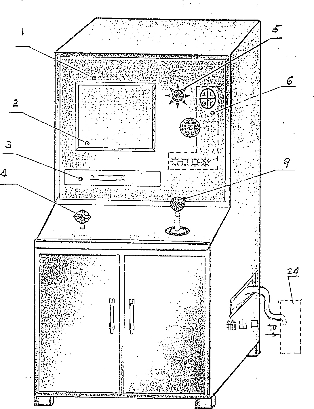
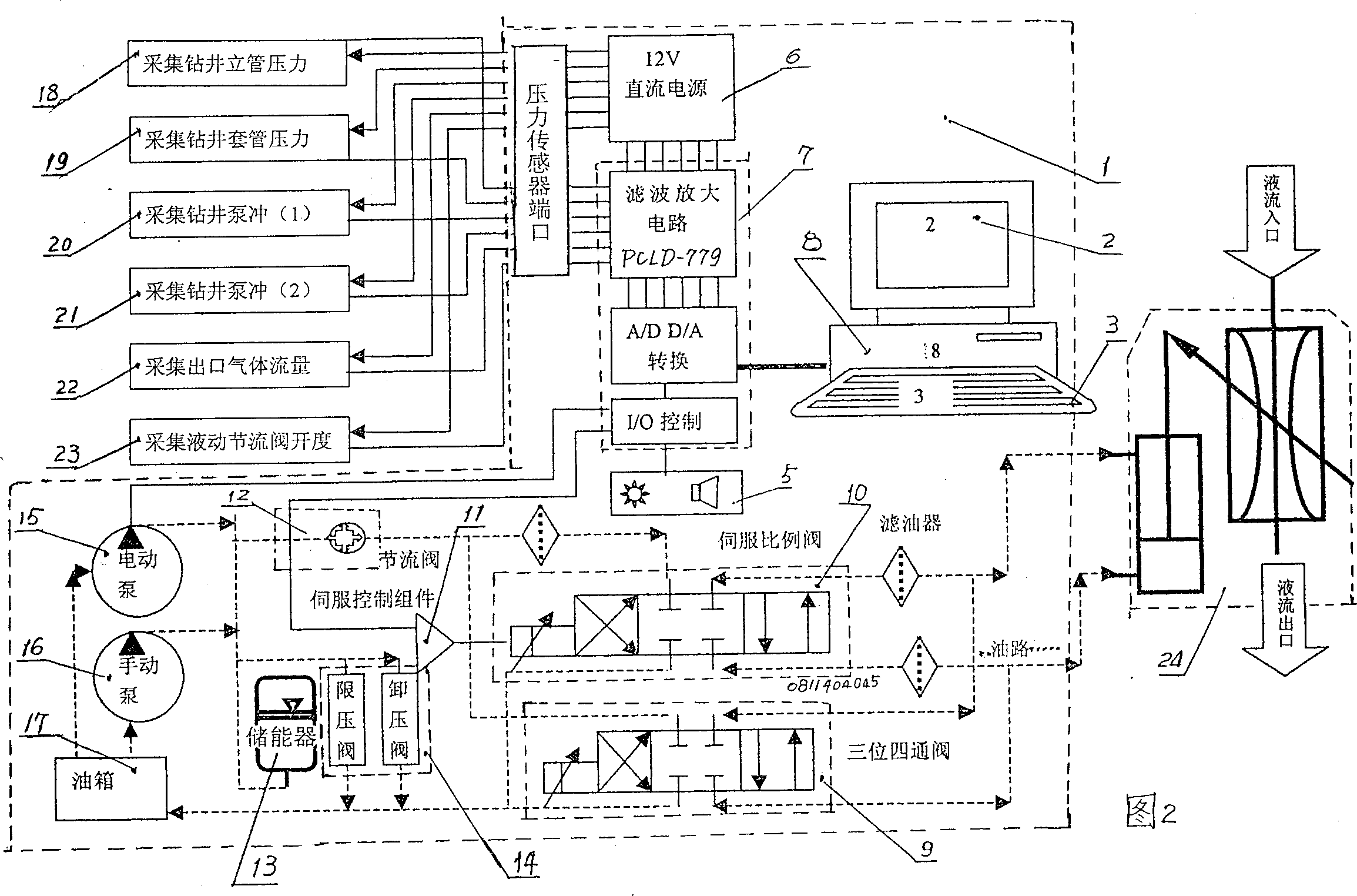
[0017] refer to figure 1 , showing the outline drawing of the main cabinet of the oil and gas drilling throttling pressure microcomputer automatic control device according to the present invention, 1 is the cabinet shell, and its front panel is provided with a computer display 2 and a keyboard box 3, and there are sound and light alarm holes 5 on the side of the panel As well as the power switch and indicator light part 6, a throttle valve knob 4 is provided on one side of the cabinet table, which is connected to the throttle valve 12 inside the cabinet, and a three-position four-way valve 9 is provided on the other side; with reference to Fig. 2, the present invention is shown The schematic diagram of the connection relationship of each component in the control system, 10 in the figure is a servo proportional valve, which is connected to the servo control component 11, and in the oil circuit controlled by oil pressure, the throttle valve 12 is respectively connected to the ele...


PUM


Abstract

The present invention relates to the autocontrol in oil and gas exploitation and the microcomputerized autocontrol system incldues: pressure sensor to measure the pressure inside the vertical pipe and the casing, displacement sensor to measure the opening of the hydraulic throttle valve, pump stroke sensor to measure pump stroke, gas flowmeter to measure the flow rate of separated gas, filter andamplifier to process to collected signals, A/D converter, microcomputer for record, storage, calculation data display and issuing control commands for regulation. The system completes the microcomputerized autocontrol of throttle pressure in underbalance well drilling and realize precise control.

Description

(1) Technical field [0001] The invention belongs to the field of automatic control for oil and gas exploration and development, in particular to a microcomputer automatic control system for oil and gas drilling throttling pressure. (2) Background technology [0002] In oil and gas exploration and development projects, in order to better protect oil and gas layers, effectively reduce the damage caused by drilling fluid to oil and gas layers, and at the same time, in order to reduce or overcome the influence of pressure difference on drilling speed, to greatly increase the mechanical speed of penetration and improve oil well performance. To effectively reduce the comprehensive cost of oil and gas development, the success of drilling requires good control of the hydraulic choke pressure, and the use of underbalanced drilling technology and the control device of the hydraulic choke manifold to perform remote control and maintain a stable well. bottom pressure to minimize the dam...

Claims


Application Information

Patent Timeline
Patent Type & Authority Applications(China)
IPC IPC(8): E21B44/00
Inventor 刘刚杨忠锋刘志国夏宏南邢纪国
Owner 刘刚
Why Eureka
Try Eureka