Probe head adapter for checking probe

A technology for detecting probes and probe heads, which is applied in the direction of measuring leads/probes, parts of electrical measuring instruments, instruments, etc., and can solve problems such as limiting the input bandwidth of probes

Inactive Publication Date: 2002-03-20
TEKTRONIX INC
View PDF3 Cites 7 Cited by
  • Summary
  • Abstract
  • Description
  • Claims
  • Application Information

AI Technical Summary

Problems solved by technology

Probe tip capacitance and inductance

Method used


Image

  • Probe head adapter for checking probe
  • Probe head adapter for checking probe
  • Probe head adapter for checking probe

Examples


Embodiment Construction

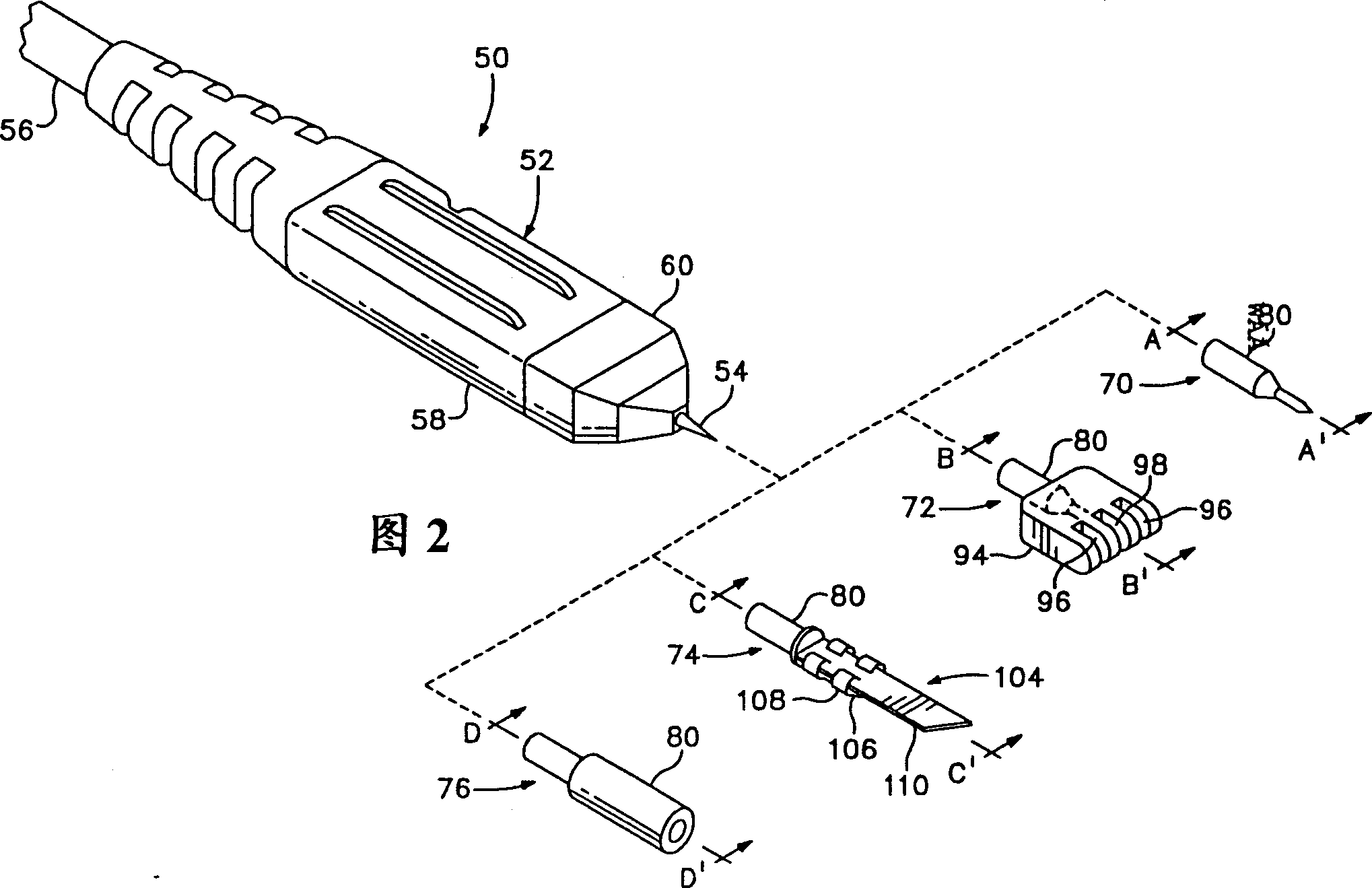
[0015] Referring to FIG. 2, this figure is a perspective view of a wideband high frequency test probe 50 for probing high bandwidth circuits. The detection probe 50 includes a probe head 52 with a probe head 54 protruding from one end of the probe. A coaxial cable 56 protruding from the other end connects the probe head 52 to a measuring instrument, such as an oscilloscope, a spectrum analyzer, a logic analyzer, and the like. The probe head 52 is provided with a conductive tubular housing 58 enclosing a substrate on which active and passive components are mounted to form the probe output circuit. Probe tip 54 and coaxial cable 56 are electrically connected to the substrate. Insulation material surrounds housing 58 and a portion of coaxial cable 56 .

[0016] To achieve wide bandwidths and multi-gigahertz frequencies, tip capacitance and inductance need to be kept to a minimum. To achieve this, the length and diameter of the probe tip 54 are reduced to the extent possible. ...


PUM


Abstract

A probe tip adapter for a measurement probe has at least a first electrically conductive element with a bore at one end and a probing contact formed on the other end. The bore of the electrically conductive element has an electrically conductive elastomer disposed therein having sufficient tensile strength, compression set, hardness, deflection force, elongation and percent recovery for repeatably securing the electrically conductive element to the probing tip of the measurement probe. The probing contact may be configured as a probing tip having a shaft that tapers at one end to a point and as a square pin adapter with a bore formed in the electrically conductive element that receives a spring contact. The probe tip adapter is useable with both single ended and differential measurement probes.

Description

[0001] This application claims the benefit of US Provisional Patent Application Serial No. 60 / 226,772, filed August 21,2000. technical field [0002] This invention relates generally to probe adapters for test probes, and more particularly to probe tip adapters that can be used with high frequency single-ended and differential test probes. Background technique [0003] Probe Tip Adapter is an accessory developed to allow inspection probes to probe different types of electronic components. The adapter can realize connection with square pins mounted on the circuit board, grounding points on the circuit board, surface leads mounted on the integrated circuit device, and the like. Model P6243 Active Detection Probe 10, manufactured and sold by Tektronix, Inc., Beaverton, OR, of Beaverton County, Ore., the assignee of the present invention, has a receptacle Type probe head 12 and ground jack 14 as shown in Figure 1, appearance design patent DES354,923 has explanation to this. Th...

Claims


Application Information

Patent Timeline
IPC IPC(8): G01R1/06G01R1/067
CPCG01R1/06788G01R1/06738
Inventor M·A·格斯福德M·W·奈廷加勒G·W·雷德
Owner TEKTRONIX INC
Why Eureka
Try Eureka