Material for shadow mask, method for production thereof, shadow mask and image tube

A shadow mask, weight technology, used in manufacturing tools, cold cathode manufacturing, electrode system manufacturing, etc.

Inactive Publication Date: 2002-04-03
TOYO KOHAN CO LTD
View PDF3 Cites 5 Cited by
  • Summary
  • Abstract
  • Description
  • Claims
  • Application Information

AI Technical Summary

Problems solved by technology

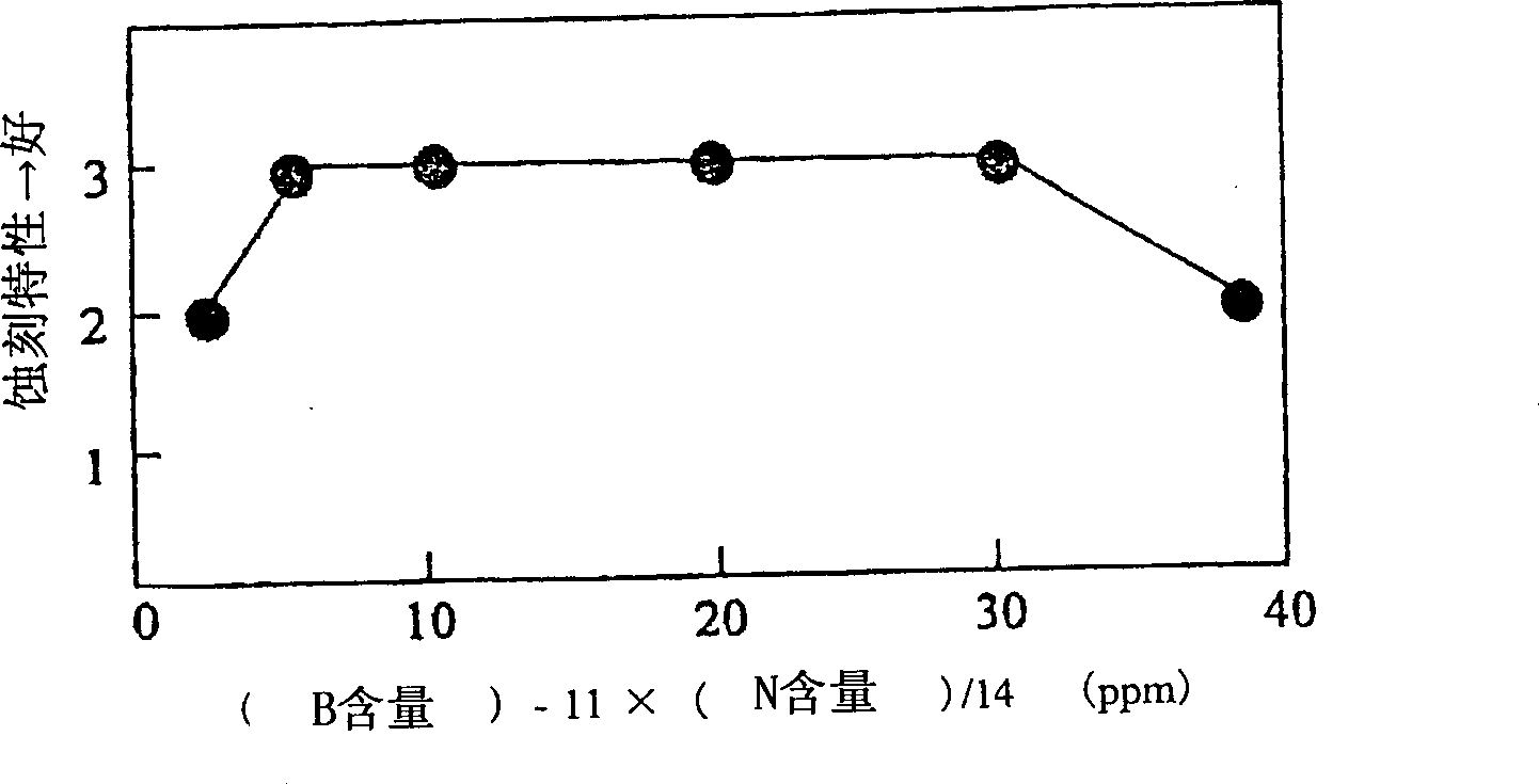
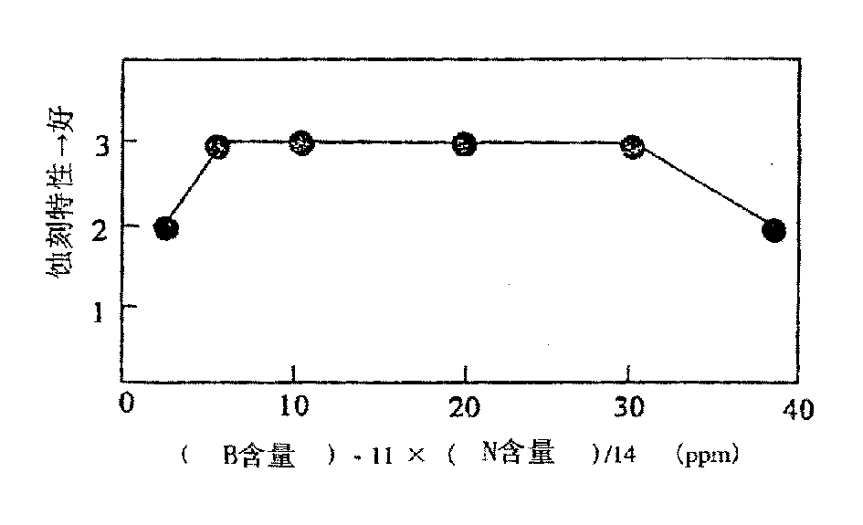
In the prior art described above, although the steel composition and annealing conditions are described, it is not enough to provide stable etching performance and punching workability to meet the requirements for shadow mask materials such as high image quality and its sharpness in recent years

Method used


Image

  • Material for shadow mask, method for production thereof, shadow mask and image tube
  • Material for shadow mask, method for production thereof, shadow mask and image tube

Examples


Embodiment

[0051] Hereinafter, examples of the present invention will be described. Steel strips having the chemical composition shown in Table 1 were hot-rolled to produce hot-rolled steel strips with a thickness of 2.3 mm. After pickling, the strip was cold-rolled into a 0.3 mm thick cold-rolled strip. In the successive annealing steps, decarburization annealing is performed under various conditions. Table 2 lists the annealing conditions and the carbon content after annealing related to each example. In addition, an ultra-thin shadow mask material with a thickness of 0.1 mm was formed by cold rolling.

[0052] Strip braided

No

Chemical composition (weight%)

C

Si

mn

P

S

Al

N

B

Fe

1

0.0021

0.03

0.36

0.017

0.017

0.041

0.0017

0.0021

margin

2

0.0021

0.02

0.22

0.017

0.018

0.045

0.0023

0.0030

margin

3

0.0024

0.02

0.30 ...


PUM

PropertyMeasurementUnit
thicknessaaaaaaaaaa

Abstract

A material for shadow mask having the following composition of components: C C21D 9 / 46 C22C 38 / 00 C22C 38 / 06 H01J 9 / 14 1 11 6 2000 / 3 / 8 1343263 2002 / 4 / 3 1110575 2003 / 6 / 4 2003 / 6 / 4 Toyo Kohan Co., Ltd. Japan Sato Taizo Ueda Toshiyuki Aoki Shinichi long chuangong 11038 The Patent Agency of the Chinese Council for the Promotion of International Trade (CCPIT) No.1 Waidajie, Fuxingmen, Beijing 100086 Japan 1999 / 3 / 12 66542 / 99 2001 / 9 / 11 PCT / JP00 / 01402 2000 / 3 / 8 WO00 / 55383 2000 / 9 / 21 Japanese

Description

technical field [0001] The present invention relates to a cold-rolled steel strip used as a material for a picture tube shadow mask, a method for manufacturing the cold-rolled steel strip, a shadow mask made of the cold-rolled steel strip, and a picture tube with the shadow mask. Background technique [0002] Cold-rolled steel strip for shadow mask materials has historically been produced using the following processing steps. That is, low carbon steel produced by a steel mill is processed through pickling and cold rolling, thereby forming a steel strip having a predetermined thickness. After degreasing, the strip is decarburized and annealed in a box annealing furnace in the wet state. Subsequently, the strip is subjected to secondary cold rolling to form a finished strip with a finished thickness. [0003] The cold-rolled steel strip produced by this method is mounted in a picture tube after being photo-etched, annealed, stamped and baked. Unless the carbon originally co...

Claims


Application Information

Patent Timeline
Patent Type & Authority Applications(China)
IPC IPC(8): C21D3/04C21D8/02C22C38/00C22C38/04C22C38/06H01J29/07
CPCC22C38/04C21D8/0257C21D3/04C22C38/002C22C38/004C22C38/06C21D8/0226H01J2229/0733H01J29/07C22C38/00H01J9/02
Inventor 佐藤台三上田利行青木晋一
Owner TOYO KOHAN CO LTD
Why Eureka
Try Eureka