R-t-b alloy, process for production of r-t-b alloy, fine powder for r-t-b rare earth permanent magnets, and r-t-b rare earth permanent magnet
Inactive Publication Date: 2010-09-16
SHOWA DENKO KK
View PDF6 Cites 14 Cited by
Summary
Abstract
Description
Claims
Application Information
AI Technical Summary
This helps you quickly interpret patents by identifying the three key elements:
Problems solved by technology
Method used
Benefits of technology
[0040]An R-T-B alloy of the present invention has a main phase, being an R2T14B phase, and an R-rich phase, and when the mean value of the concentration of Dy and/or Tb in the whole of the R-T-B alloy is defined as the average concentration, an area of 60% or more of the area of the main phase in an arbitrary cross-section of the R-T-B alloy contains Dy and/or Tb at the average concentration or higher. Since the concentration of Dy and/or Tb in the main phase is high, and the dispersion of the concentration of Dy and/or Tb in the main phase is low, it is possible to realize an R-T-B rare earth permanent magnet with low dispersion of its magnetic properties and excellent uniformity of magnetization.
[0041]Since a process for producing an R-T-B alloy of the present invention has a casting step that uses a strip casting method, and a temperature maintaining heat
Problems solved by technology
However, a reduction is required in heavy rare earth elements added to rare earth magnets because of resource limitations.
Accordingly, if the distribution state of the R-rich phase in the molded magnet is abnormal, it causes localized sintering failure and reduction of magnetism.
Furthermore, a problem occurring in casting R-T-B alloy is that α-Fe is formed in the cast alloy. α-Fe degrades the pulverizing efficiency when the alloy is being pulverized.
Moreover,
Method used
Image
Click on the blue label to locate the original text in one second.
Reading with bidirectional positioning of images and text.
Examples
example 1
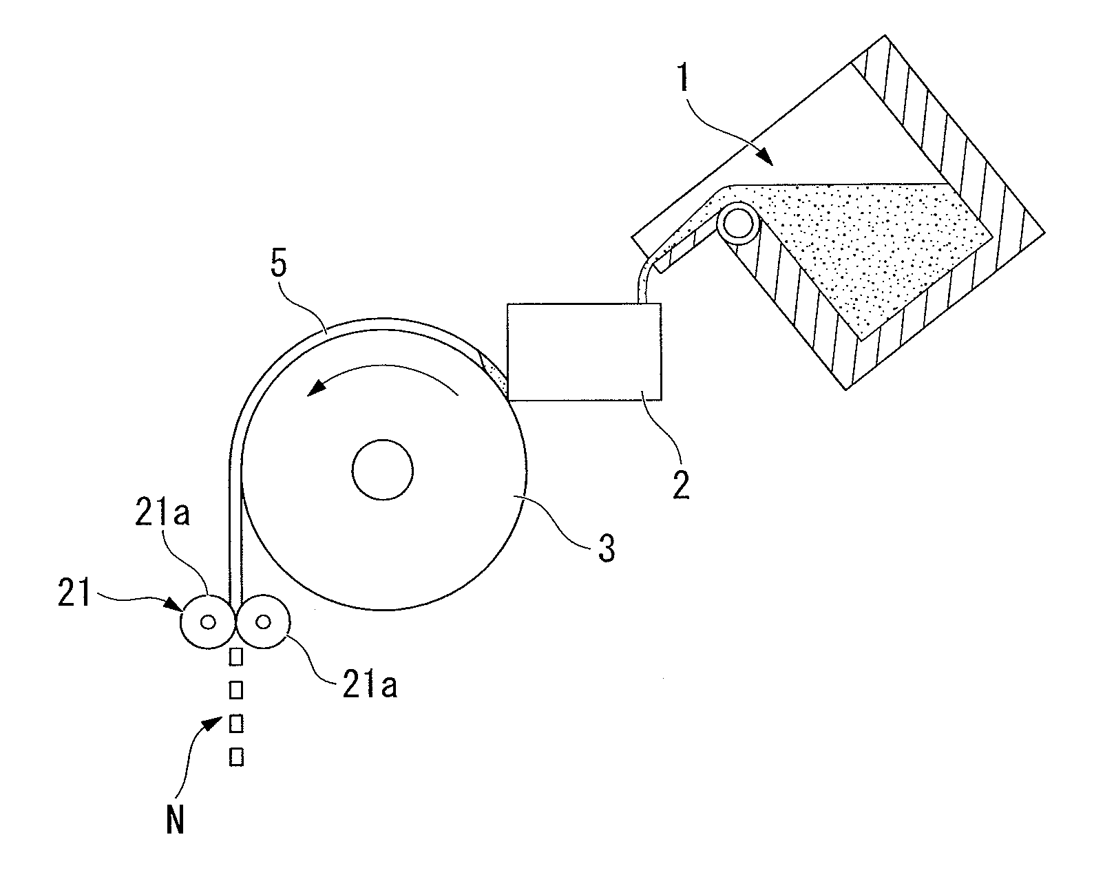
[0106]A raw material with a composition of Nd: 25%, Pr: 6%, Dy: 2%, B: 0.99%, Co: 1.0%, Al: 0.15%, Cu: 0.1.0%, Ga: 0.1%, and the remainder being Fe, as weight ratios, was weighed, poured into the refractory crucible 1 in the manufacturing apparatus shown in FIG. 1, which was made from alumina, and melted in an atmosphere of argon gas at 1 atmospheric pressure using a high frequency melting furnace to form a molten metal alloy. Next, the molten metal alloy was supplied to the casting roller 3 (cooling roller) via the tundish 2, cast using an SC method, and was crushed using the crushing equipment 21 in order to form cast alloy flakes of the R-T-B alloy. Then it was transferred to the temperature maintaining container of the temperature control apparatus to start the temperature maintaining heat treatment step.
[0107]The rotating speed of the casting roller was 1.0 m / s, the temperature of the alloy when it detached from the cooling roller was 800° C., the temperature of the alloy when ...
example 2
[0128]Except for using a raw material with a composition of Nd: 22%, Pr: 6%, Dy: 5%, B: 0.99%, Co: 1.0%, Al: 0.15%, Cu: 0.10%, Ga: 0.1%, and the remainder being Fe, as weight ratios, casting and crushing were performed similarly to example 1, and a temperature maintaining heat treatment step was performed similarly to example 1 to obtain cast alloy flakes of R-T-B alloy.
example 3
[0134]Except for using a raw material with a composition of Nd: 17%, Pr: 5%, Dy: 9%, B: 0.92%, Co: 2.0%, Al: 0.15%, Cu: 0.10%, Ga: 0.1%, and the remainder being Fe, as weight ratios, casting and crushing were performed similarly to example 1, and a temperature maintaining heat treatment step was performed similarly to example 1 to obtain cast alloy flakes of R-T-B alloy.
PUM
Property
Measurement
Unit
Temperature
aaaaa
aaaaa
Temperature
aaaaa
aaaaa
Temperature
aaaaa
aaaaa
Abstract
An R-T-B alloy used in a rare earth permanent magnet, where R is at least one element selected from rare earth elements including Y, which contains Dy and/or Tb as an essential element, T is a metal comprising Fe as an essential element, and B is boron, comprising: a main phase being an R2T14B phase, and an R-rich phase; and when a mean value of the concentration of Dy and/or Tb in the whole of said R-T-B alloy is defined as an average concentration, an area of 60% or more of an area of said main phase in an arbitrary cross-section of said R-T-B alloy contains said Dy and/or Tb at the average concentration or higher; a process for the production of the R-T-B alloy; a fine powder for R-T-B rare-earth permanent magnets which is prepared from the R-T-B alloy: R-T-B rare earth permanent magnet, and motors.
Description
TECHNICAL FIELD[0001]The present invention relates to an R-T-B alloy, a process for the production of an R-T-B alloy, a fine powder for R-T-B rare earth permanent magnets, and an R-T-B rare earth permanent magnet. In particular, it relates to an R-T-B alloy and a fine powder for R-T-B rare earth permanent magnets whereby R-T-B rare earth permanent magnets with excellent uniformity of magnetization can be obtained.BACKGROUND ART[0002]In recent years, demand for motors using rare-earth magnets has been increasing against a background of strong demand for energy saving. In rare-earth magnets for use in motors, heavy rare earth elements such as Dy, Tb and the like are utilized in order to improve heat resistance. However, a reduction is required in heavy rare earth elements added to rare earth magnets because of resource limitations. Furthermore, if heavy rare earth elements are added, the remanence of a sintered magnet is reduced, so that the energy of the rare-earth magnet itself is r...
Claims
Application Information
Patent Timeline
Application Date:The date an application was filed.
Publication Date:The date a patent or application was officially published.
First Publication Date:The earliest publication date of a patent with the same application number.
Issue Date:Publication date of the patent grant document.
PCT Entry Date:The Entry date of PCT National Phase.
Estimated Expiry Date:The statutory expiry date of a patent right according to the Patent Law, and it is the longest term of protection that the patent right can achieve without the termination of the patent right due to other reasons(Term extension factor has been taken into account ).
Invalid Date:Actual expiry date is based on effective date or publication date of legal transaction data of invalid patent.