
Colour CRT integrated with deflection circuit

A cathode ray tube and deflection circuit technology, which is applied in the direction of cathode ray tube indicators, cathode ray/electron beam tube circuit components, cathode ray/electron beam tube circuit layout, etc., which can solve the problem of increased manufacturing cost of model products and deflection system quality and reduced productivity

Inactive Publication Date: 2002-04-24
LG ELECTRONICS INC
View PDF0 Cites 0 Cited by
  • Summary
  • Abstract
  • Description
  • Claims
  • Application Information

AI Technical Summary

Problems solved by technology

In this case, since a large number of deflection yokes must be manufactured for one type of color CRT, the quality and productivity of the deflection yokes are reduced, and the manufacturing cost of the type product is increased.

Method used


Image

  • Colour CRT integrated with deflection circuit
  • Colour CRT integrated with deflection circuit
  • Colour CRT integrated with deflection circuit

Examples


Embodiment Construction

[0031] Hereinafter, the present invention will be described in detail in combination with preferred embodiments with reference to the accompanying drawings. Regarding the reference numerals, the same reference numerals denote corresponding parts throughout the several figures.

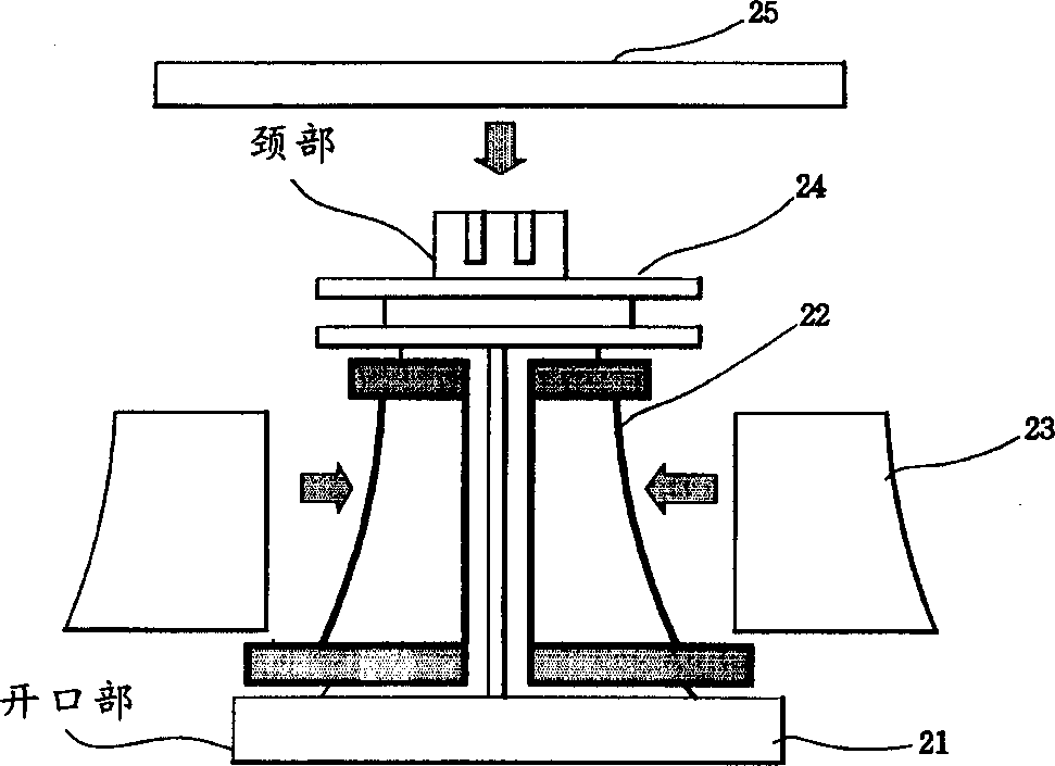
[0032] Image 6 is a schematic diagram of a color CRT (cathode ray tube) integrated with a deflection circuit according to the present invention. Image 6 In, a synchronous signal separation circuit for separating horizontal and vertical synchronous signals from synchronous signals and a synchronous signal separation circuit for horizontally and vertically deflecting three electron beams of R (red), G (green) and B (blue) colors are mounted on the circuit board deflection circuit, and the circuit board is mounted on the deflection yoke.

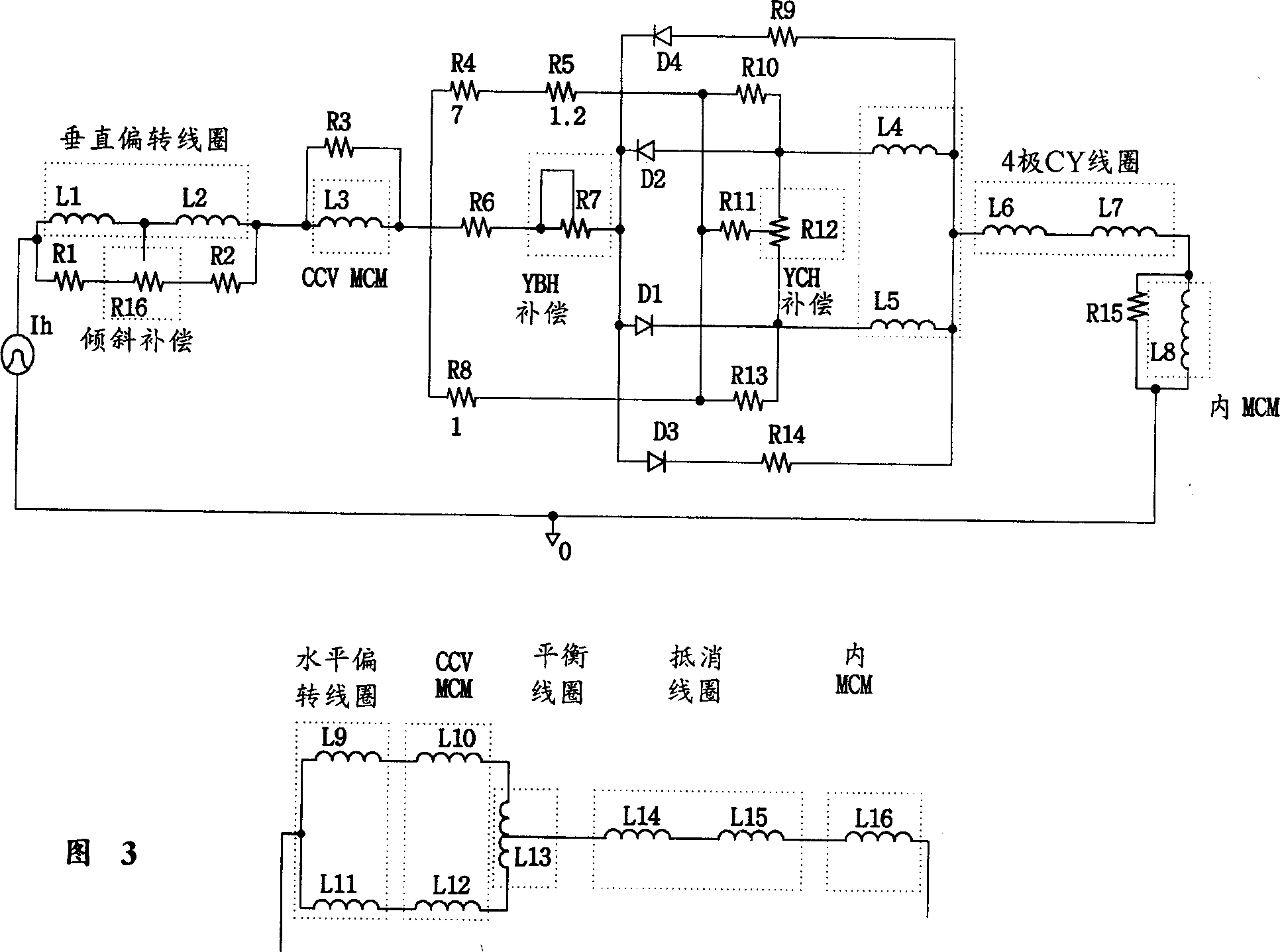
[0033] Figure 7 is a circuit diagram according to the present invention. Figure 7 Among them, the chassis includes a video signal processor, a signal supply con...


PUM


Abstract

Disclosed is a color CRT (Cathode Ray Tube) integrated with deflection circuit. The color CRT includes a sync signal separation and deflection circuit board attached on at least a portion of the color CRT. The sync signal separation and deflection circuit board includes a sync signal separation circuit for separating sync signal from video signal to regenerate video signal into the same contents, a horizontal deflection circuit for impressing horizontal deflection current onto a horizontal deflection coil and a vertical deflection circuit for impressing vertical deflection current onto a vertical deflection coil. The color CRT, which has the sync signal separation and deflection circuit attached on at least a portion of the color CRT, allows a one-to-one matching of the deflection circuit and a deflection yoke by removing the causes of DY fluctuation due to the change of set condition. Moreover, the color CRT reduces a manufacturing cost by mass production of the deflection circuit and the deflection yoke and facilitates improvement of quality.

Description

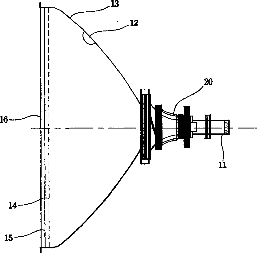
technical field [0001] The present invention relates to a color CRT (cathode ray tube) integrated with a deflection circuit, and more particularly to a color CRT having a deflection circuit integrally formed with the color CRT, wherein the deflection circuit is used to drive a deflection yoke mounted on the color CRT, by pre-eliminating The reason why the deflection yoke fluctuates with changes in overall machine conditions is that the deflection circuit does not have to be mounted on the substrate of the visual processor with the chassis. Background technique [0002] like figure 1 As shown, a color CRT (cathode ray tube) includes a panel 16 mounted on the front surface of the CRT; phosphor surfaces coated with R (red), G (green) and B (blue) color phosphors on the inner surface of the panel 15; a shadow mask 14 arranged at the rear of the fluorescent surface for selecting the color of the electron beam incident on the fluorescent surface; a cone 13 that is connected to th...

Claims


Application Information

Patent Timeline
IPC IPC(8): H01J31/06G09G1/04H01J29/96
CPCH01J29/96G09G1/04H01J31/06
Inventor 李永旭金智显
Owner LG ELECTRONICS INC
Learn More