Particle accelerator

A technology of particle accelerator and voltage multiplier, which is applied in DC voltage accelerators, X-ray tubes, discharge tubes, etc., and can solve problems such as damage to insulators, increase in outer diameter, and obstruction

Inactive Publication Date: 2002-05-22
IND CONTROL MACHINES
View PDF1 Cites 7 Cited by
  • Summary
  • Abstract
  • Description
  • Claims
  • Application Information

AI Technical Summary

Problems solved by technology

In this way, the electric field on the insulator c may locally reach a value high enough to destabilize the cathodic current due to the gate effect, and sometimes even damage the insulator
[0009] Second, the potential between anode a and cathode b will not be uniformly distributed
H

Method used


Image

  • Particle accelerator
  • Particle accelerator
  • Particle accelerator

Examples


Embodiment Construction

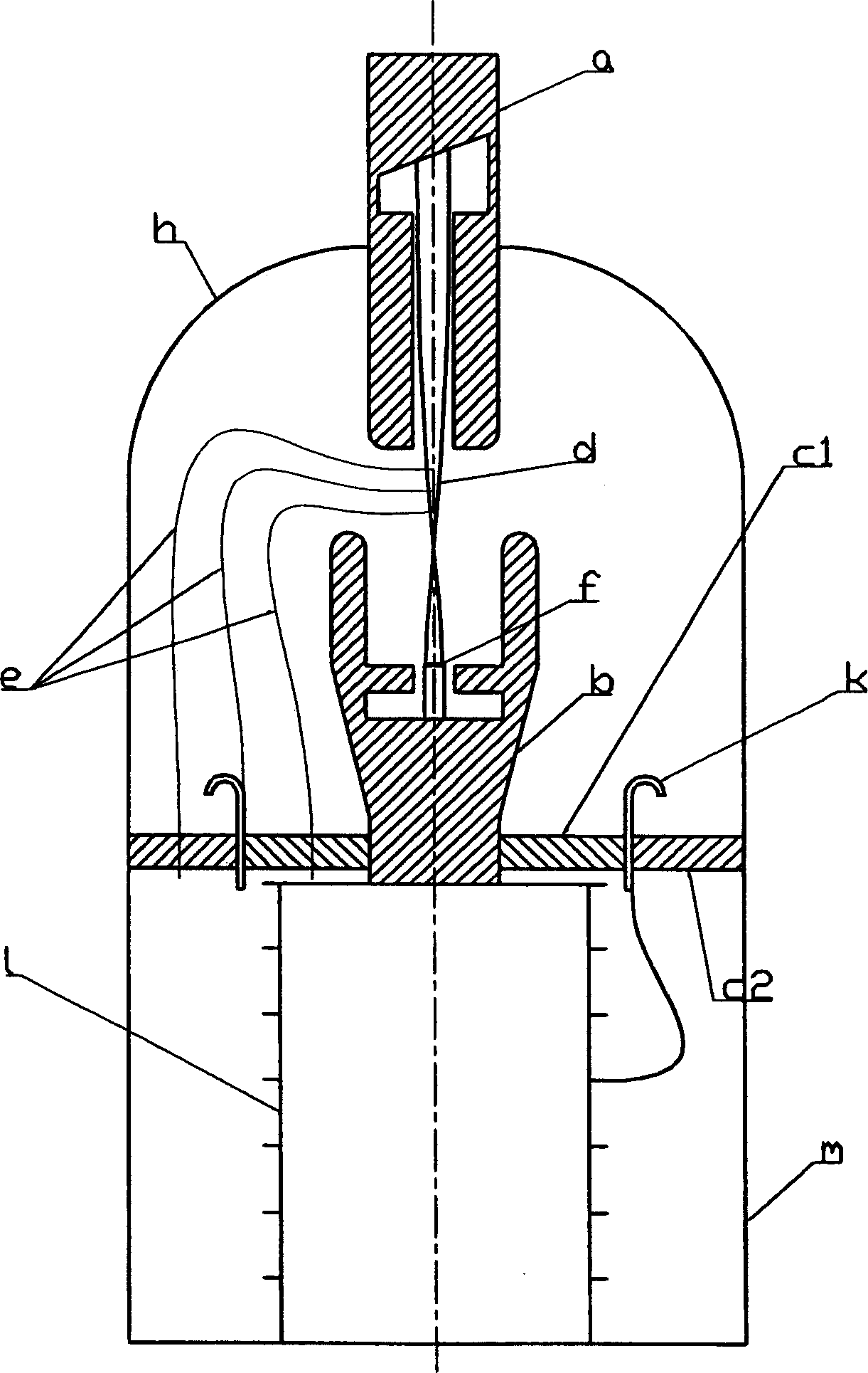
[0021] in Figure 6 An example of the voltage multiplier used in the device is shown in Figure 4c in. In particular, the multiplier includes 7 stages, and how each electrode k1 to k6 is connected to each stage of the multiplier is schematically illustrated.

[0022] As a result, the insulator is divided into as many parts as there are stages in the multiplier of the supply tube, exactly as Figure 5 The example is shown. The essential difference is that in the present invention, the voltage multiplier can be arranged in the space including the X-ray tube, which can greatly reduce the size of the component, especially the outer diameter. In other words, the voltage multiplier is encapsulated in an insulator.

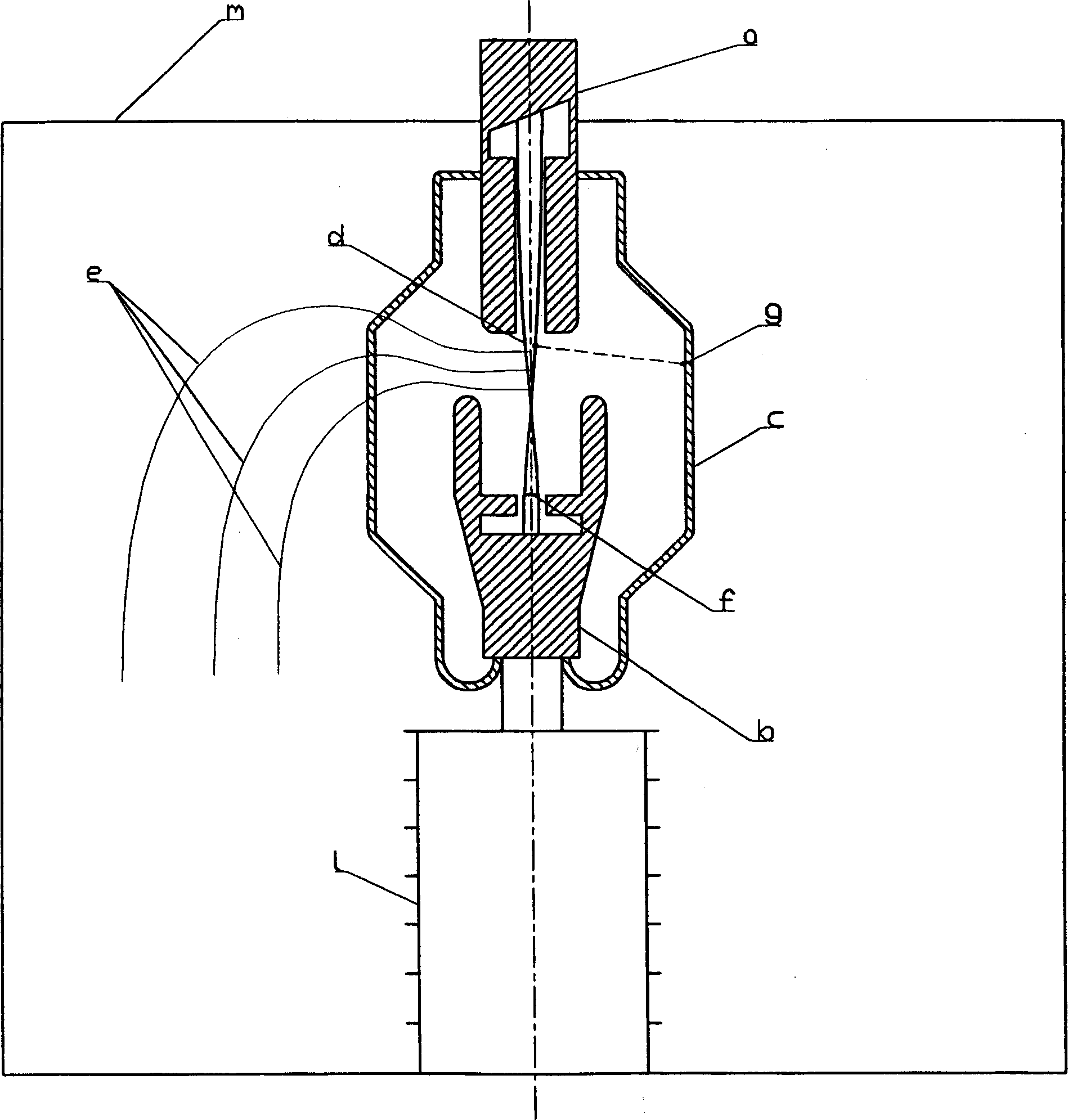
[0023] The reasons for the size reduction are compared image 3 with 6 Can be clearly seen. image 3 In represents the known solution, it can be seen that in order to reduce the electric field, the equipotential lines must be completely separated along the radius passing thr...


PUM


Abstract

The invention relates to a particle accelerator. The accelerator comprises a chamber (h) made of conducting material having a central axis; an anode (a) connected electrically to the chamber along the central axis; a cathode (b) housed in the chamber along the central axis; an insulating element (c) connecting the cathode to the chamber, the insulating element comprising several sections separated by electrodes (k1 to k6). The insulator lies inside the chamber (h) along the central axis in the extension of the region formed by the anode (a) and the cathode (b).

Description

Technical field [0001] The invention relates to a particle accelerator, particularly an electron accelerator. technical background [0002] For more than one hundred years, the characteristics of X-rays have been widely used. This is because the radiation has the characteristics of being able to penetrate the material, and the absorption rate depends on the thickness and characteristics of the material to be penetrated at the same time. In this way, if any object is exposed to X-rays, and if a device can be used to restore the dose level point by point behind the object, this method can be used to obtain information about its internal properties, and its defects that cannot be seen from the outside Information, or whether it contains impurities. [0003] The most well-known application is of course medicine, but X-rays are also widely used in industry to detect defects or impurities, and to inspect luggage or various packages in the security field. [0004...

Claims


Application Information

Patent Timeline
IPC IPC(8): H01J35/02H05G1/02H05H5/02
CPCH01J35/02H05H5/02H05G1/02H01J2235/165
Inventor 阿莱恩·保鲁斯雅克·古福克斯
Owner IND CONTROL MACHINES
Why Eureka
Try Eureka