
Insulated gate bipolar transistor IGBT drive protection circuit

A technology for driving protection circuits and bipolar transistors, which can be applied to emergency protection circuit devices, electronic switches, electrical components, etc., and can solve problems such as low reliability of frequency converters

Inactive Publication Date: 2002-06-19
SOMER LEROY ELECTRO TECH FUZHOU CO LTD
View PDF0 Cites 65 Cited by
  • Summary
  • Abstract
  • Description
  • Claims
  • Application Information

AI Technical Summary

Problems solved by technology

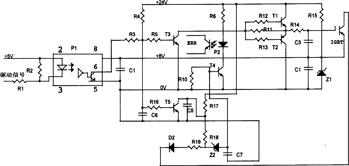
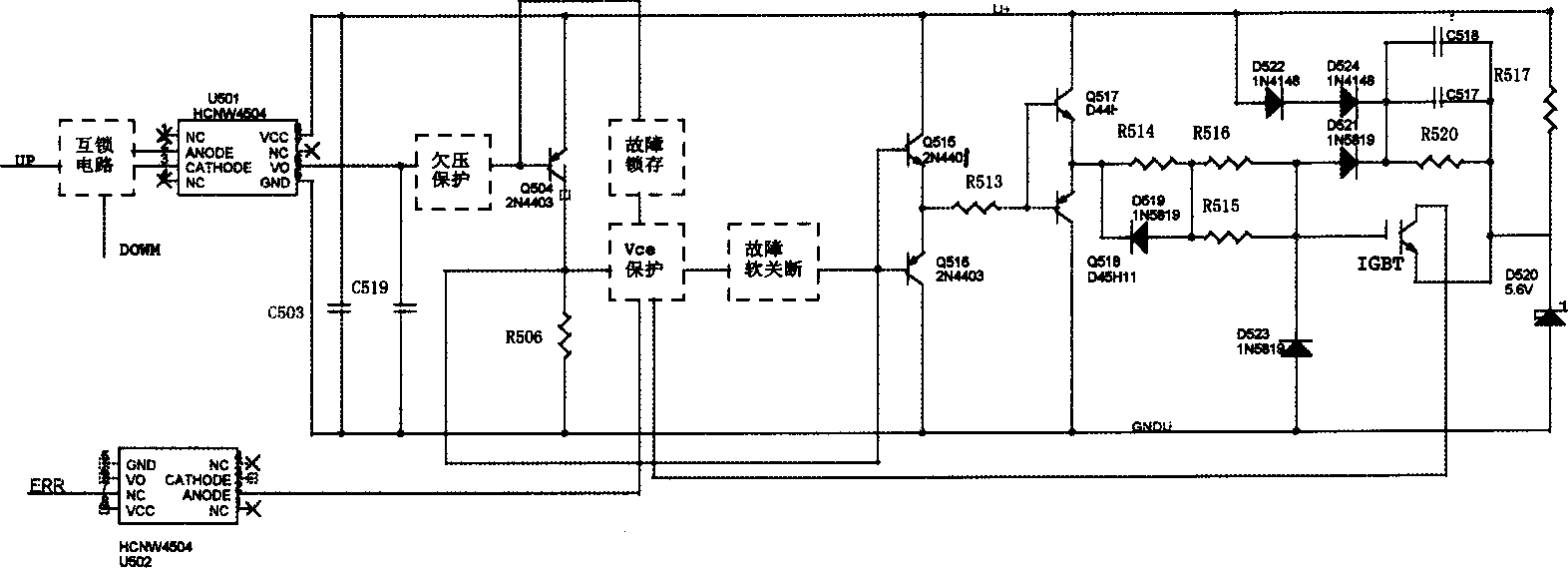
[0002] At present, because the insulated gate bipolar transistor IGBT is easy to drive and can handle large current and high voltage at a high switching frequency, the insulated gate bipolar transistor IGBT is mostly used in high-power inverters and switching power supplies at home and abroad. Switching devices, so the IGBT drive protection circuit has become an important circuit related to the reliability of the inverter. The IGBT drive protection circuit used by the existing inverter has a variety of forms due to different design ideas. like figure 1 and figure 2 Shown are two typical drive protection circuits, where figure 1 The circuit structure shown is simple and has the function of driving power supply undervoltage protection. figure 2 The circuit structure shown is a bit complicated, and it has the protection function of IGBT collector-emitter voltage Vce, but a comprehensive analysis of various current circuit schemes shows that various existing circuit schemes have their own design emphases, but None of the circuit schemes has a perfect protection function, resulting in low reliability of the inverter and inconvenience to use

Method used


Image

  • Insulated gate bipolar transistor IGBT drive protection circuit
  • Insulated gate bipolar transistor IGBT drive protection circuit
  • Insulated gate bipolar transistor IGBT drive protection circuit

Examples


Embodiment Construction

[0017] Such as image 3 ~Shown in Figure 4, the present invention mainly comprises:

[0018] A power supply U for providing constant voltage + ;

[0019] An insulated gate bipolar transistor IGBT for controlling load on-off;

[0020] An upper and lower bridge drive signal circuit for driving the optocoupler U 501 ;

[0021] Optocoupler U 501 , its input terminal is connected with the drive signal circuit of the upper and lower bridges, and its output terminal generates a control voltage to the switching transistor Q 504 the base;

[0022] A switching triode control circuit is used to generate a switching signal as the input voltage of the amplifying circuit, which is mainly composed of the switching transistor Q 504 and resistor R 506 composition, where the switching transistor Q 504 The base of the optocoupler U 501 Connected to the output terminal, its emitter is connected to the power supply, its collector is connected to the amplifier circuit and passed through t...


PUM


Abstract

The invention relates to a protection circuit driven by insulated gate bipolar transistor (IGBT). It is composed of power supply, IGBT, a signal circuit driven by upper and lower bridges, light coupler, a control circuit with a switch triode, an amplifying circuit for driving signal, a protection circuit for detecting and adjusting the voltages between collector and emitter of IGBT. Said protection circuit includes a short circuit protection circuit, fault latching circuit and fault soft switch off circuit. When the voltage of collector-emitter of IGBT is abnormal, the voltage of insulated gate of IGBT is adjusted to lower than threshold voltage, by the operation of short circuit protection circuit as well as control and amplifying circuit. Thus the IGBT is cut-off and the close latching is realized by that fault latching circuit. It guarantees to close off IGBT before CPU receives the fault signal and closes off driving signal.

Description

technical field [0001] The invention relates to a drive protection circuit of an insulated gate bipolar transistor (IGBT--Insulated Gate Bipolar Transistor), in particular to a drive protection circuit of an insulated gate bipolar transistor IGBT used as a power switching device in a frequency converter. Background technique [0002] At present, because the insulated gate bipolar transistor IGBT is easy to drive and can handle large current and high voltage at a high switching frequency, the insulated gate bipolar transistor IGBT is mostly used in high-power inverters and switching power supplies at home and abroad. Switching devices, so the IGBT drive protection circuit has become an important circuit related to the reliability of the inverter. The IGBT drive protection circuit used by the existing inverter has a variety of forms due to different design ideas. Such as figure 1 and figure 2 Shown are two typical drive protection circuits, where figure 1 The circuit struc...

Claims


Application Information

Patent Timeline
Patent Type & Authority Applications(China)
IPC IPC(8): H02H7/122H03K17/08
Inventor 徐学海李玲刘玉虎杜亚东邱文渊
Owner SOMER LEROY ELECTRO TECH FUZHOU CO LTD
Learn More