Transfer mechanism, image-forming device using same and method for mfg. transfer device

An imaging device and transfer printing technology, applied to the equipment of the electric recording process using the charge pattern, the electric recording process using the charge pattern, and the electric recording technique, etc., can solve the problems of the reduction of the surface reflectivity of the transfer roller, large rotation load, Problems such as toner contamination of the transfer roller

Inactive Publication Date: 2002-07-24
FUJIFILM BUSINESS INNOVATION CORP
View PDF3 Cites 9 Cited by
  • Summary
  • Abstract
  • Description
  • Claims
  • Application Information

AI Technical Summary

Problems solved by technology

However, this type of transfer mechanism is technically disadvantageous in that as the recording material moves, more external additives for toner adhere to the surface of the transfer roller, increasing the distance between the cleaning blade and the transfer roller. friction coefficient of the surface, and thus apply a greater rotational load to the transfer roller
[0011] The technical disadvantage of this strength control method is that even if the strength patch transferred to the transfer roller can be removed with a cleaning blade, the remaining toner will gradually pollute the surface of the transfer roller, and the reflection on the surface of the transfer roller The rate is reduced, therefore, the detection of intensity patches cannot be accurately performed
Therefore, there is a worrying case that when the transfer is performed under a high electric field during OHP paper or board or double-sided printing, a sufficient transfer electric field cannot be obtained, causing imperfect transfer
[0020] Even if an epoxy resin layer having high abrasion resistance is provided on the surface of the metal roller instead of the polyimide resin layer, there is still a worrying situation that even if the cleaning property of the metal scraper can be kept good, the Oxygen layers have a particularly high electrical resistance, and charge buildup can cause imperfect transfers like polyimide resin layers

Method used


Image

  • Transfer mechanism, image-forming device using same and method for mfg. transfer device
  • Transfer mechanism, image-forming device using same and method for mfg. transfer device
  • Transfer mechanism, image-forming device using same and method for mfg. transfer device

Examples


no. 1 example

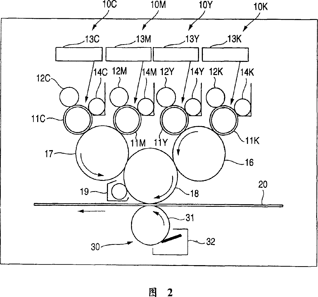
[0112] FIG. 2 is a schematic diagram showing the overall structure of an imaging device according to a first embodiment of the present invention.

[0113] In FIG. 2 , the image forming apparatus is, for example, an intermediate transfer type tandem image forming apparatus, adopts an electrophotographic method, and includes four image forming units 10 (specifically, 10K, 10Y, 10M, and 10C), and among the four image forming units, respectively Black (K), yellow (Y), magenta (M) and cyan (C) toner images are formed.

[0114] Each image forming unit 10 (10K-10C) includes a photosensitive drum 11 (11K-11C) on which an electrostatic latent image is formed and supported. An electrophotographic mechanism such as a charging mechanism 12 (12K-12C) (charging roller in this example) for charging the photosensitive drum 11 is provided around the photosensitive drum 11 for forming colors corresponding to the respective color components on the charged photosensitive drum 11. The exposure me...

no. 2 example

[0174] Fig. 10 is a schematic diagram of an essential part of a second embodiment of an image forming apparatus to which the present invention is applied.

[0175] In FIG. 10, the basic structure of the image forming apparatus is almost the same as that of the first embodiment, but the structure of the transfer mechanism 30 is different from that of the first embodiment. In the case where the constituent elements are the same as those of the first embodiment, the same reference numerals are used and further description thereof is omitted.

[0176] In this embodiment, unlike the first embodiment, the transfer roller 31 of the transfer mechanism 30 includes an adjustment resistance layer 315 made of, for example, polyurethane formed on a roller (core) 311 made of a metal such as aluminum. and a protective resin layer 314 made of epoxy resin with high surface abrasion resistance, which is formed on the adjustment resistance layer 315 .

[0177] In this embodiment, the protective...

no. 3 example

[0189] FIG. 11A is a schematic diagram showing an essential part of a third embodiment of an imaging apparatus to which the present invention is applied.

[0190] In FIG. 11A , unlike the first and second embodiments, a transfer mechanism 30 includes a transfer belt 33 instead of a transfer roller 31 .

[0191] The transfer belt 33 shown in FIG. 11A includes a belt member 333 having a protective resin layer 333a made of polyimide formed at least on its surface and an adjustment resistance layer 333b as a base layer, and the belt member is wound around a supporting roller 331. and 332. A bias roller 334 that applies a transfer bias is disposed opposite to the intermediate transfer drum 18 with the belt 333 interposed therebetween.

[0192] A belt cleaner 34 (having a metal blade 342 ) is disposed opposite to the backup roller 332 of the transfer belt 33 . The metal scraper 342 is provided in contact with the surface of the transfer belt 33 to clean the surface of the transfer...


PUM


Abstract

A transfer device for transferring an image on an image carrier 1 to a recording material 2, the transfer device comprises a transferring member 4 adapted to nip and convey the recording material 2 between the transferring member 4 and the image carrier 1, a guard resin layer 5 having a surface microhardness not smaller than surface microhardness corresponding to polyimide, the guard resin layer 5 provided on a surface of the transferring member 4, and an adjustment resistance layer 6 provided as a ground layer of the guard resin layer 5, the adjustment resistance layer 6 adapted to inhibit an accumulation of charge in the guard resin layer 5. Or, the guard resin layer 5 made of an epoxy resin is provided on the surface of the transferring member 4, the adjustment resistance layer 6 having a smooth interface with the guard resin layer 5, the adjustment resistance layer 6 adapted to inhibit accumulation of charge in the guard resin layer. Furthermore, a scraper 8 for cleaning is provided on the surface of the transferring member 4 so as to contact with the surface of the transferring member. An image-forming apparatus is constructed by using the transferring device.

Description

technical field [0001] The invention relates to a transfer mechanism for transferring an image on an image carrier to a recording material. In particular, the present invention relates to an improvement of a transfer mechanism including a transfer member for transferring a recording material through a gap between the image carrier and the transfer member; and to an image forming apparatus using the transfer member and manufacturing a transfer member. method of printing. Background technique [0002] By way of example below, a conventional image forming apparatus has been arranged to operate in an electrophotographic processing method comprising the steps of forming an electrostatic latent image on an image carrier (image carrier broadly includes: a latent image carrier such as a photosensitive drum, a latent combination of an image carrier and an intermediate transfer drum for intermediate transfer and holding of an image on a latent image carrier); deve...

Claims


Application Information

Patent Timeline
Patent Type & Authority Applications(China)
IPC IPC(8): G03G15/16
CPCG03G2215/0119G03G15/1685G03G2215/1652G03G2215/0177G03G15/16
Inventor 佐藤昌宏三桥利彦北河裕介山井和也山本隆一大川弘幸三宅弘二松本晃一河合刚志森田章一增渕富志雄
Owner FUJIFILM BUSINESS INNOVATION CORP
Why Eureka
Try Eureka