
Individual element photoelectric measuring device for pane object

A technology for measuring objects and objects, which is applied in measuring devices, color measuring devices, optical devices, etc., and can solve problems such as large distances

Inactive Publication Date: 2002-08-14
GELETEG MANKEBES
View PDF0 Cites 16 Cited by
  • Summary
  • Abstract
  • Description
  • Claims
  • Application Information

AI Technical Summary

Problems solved by technology

It is not possible to use a conventional camera at a practically achievable size, because the distance between the light source and the camera and the object under test or the object to be measured is too large

Method used


Image

  • Individual element photoelectric measuring device for pane object
  • Individual element photoelectric measuring device for pane object
  • Individual element photoelectric measuring device for pane object

Examples


Embodiment Construction

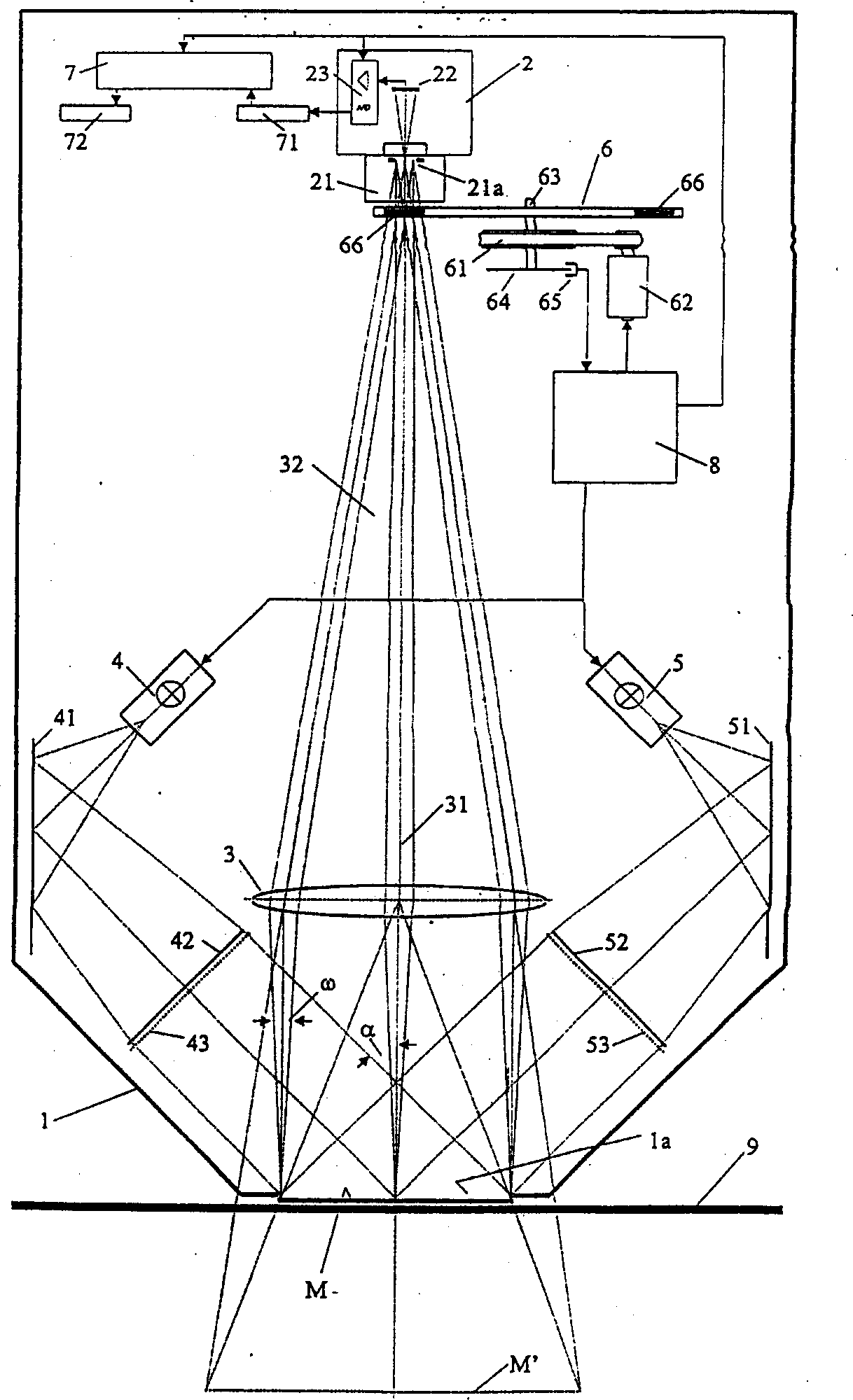
[0026] Such as figure 1 As shown, the measuring device according to the first preferred embodiment of the present invention comprises a light-tight housing 1 with a measuring window 1a, a camera 2, a remote lens 3 preferably configured as a Fresnel lens, two A flashlight source 4 and 5, two redirecting mirrors 41 and 51, two illumination lenses 42 and 52 preferably configured as Fresnel lenses, two color mixing filters 43 and 53 at the illumination lenses, filter Light wheel 6 , belt drives 61 , 62 , angle encoder 64 connected to shaft 63 of filter wheel 6 with associated sensor 65 , data processor 7 and central processing controller 8 . Preferably, the data processor 7 and the central processing controller 8 are implemented by a digital computer, but they can also be arranged outside the casing 1 of course.

[0027] The video camera 2 has the usual structure comprising, as relevant part of the invention, a standard imaging lens 21, an image sensor 22 in the form of a two-dim...


PUM


Abstract

The device for the pixel-by-pixel photoelectric measurement of a planar measured object includes projection means for the imaging of the measured object onto a two-dimensional CCD image sensor, filter means provided in the imaging light path for the wavelength selective filtering of the measuring light impinging on the image sensor, signal processing means for the processing of the electrical signals produced by the image sensor and for the conversion thereof into corresponding digital raw measured data, as well as data processing means for the processing of the raw measured data into image data representing the colors of the individual image elements of the measured object. Furthermore, illumination means are provided which include a Fresnel lens, which illuminate the measured object with at least one essentially parallel light bundle under an angle of incidence of essentially 45 DEG + / -5 DEG . The projection means which include at least one tele-lens constructed as a Fresnel lens, are constructed as tele-centrical imaging optics, which image each point of the measured object under essentially the same angle of observation of essentially 0 DEG and with essentially the same aperture angle of essentially maximally 5 DEG onto the light converter element array. The data processing means carry out extensive correction measures.

Description

technical field [0001] The invention relates to a pixel-by-pixel photoelectric measuring device for a planar or flat measured object or object to be measured. Background technique [0002] So-called scanners are used in particular in the graphics industry for the photoelectric scanning of planar objects to be measured pixel by pixel. They consist of a measuring head that is movable relative to the 1D or 2D measured object, which captures and converts the pixel-by-pixel spectral omission of the measured object or the measured object by means of the 0° / 45° measuring geometry for the corresponding electrical signal. Scanners equipped with fiber optic systems and capable of measuring complete image lines at once are also known. However, the following scanners are not known: large measured surfaces can be measured pixel by pixel without relative movement between the measuring head and the measured object, and have the advantages of color measurement and color measurement under ...

Claims


Application Information

Patent Timeline
Patent Type & Authority Applications(China)
IPC IPC(8): G01B11/00G01J3/02G01J3/28G01J3/36G01J3/51G01J3/52G01N21/25G01N21/27G01N21/31G06T1/00G06T5/00H04N1/48H04N1/60H04N9/04
CPCG01N2021/3174G01N21/274G01N21/27G01J3/0208G01J3/52G01J3/02G01J3/2803G01J3/2823G01J3/51G01N21/251G01J3/524G01J3/36G01J3/28
Inventor 汉斯·奥特
Owner GELETEG MANKEBES
Learn More