Multi-layer impedance
A technology of impedance components and magnetic layers, applied in electrical components, components of transformers/inductors, inductors, etc., can solve problems such as different magnetic permeability and changes in electrical characteristics
- Summary
- Abstract
- Description
- Claims
- Application Information
AI Technical Summary
Problems solved by technology
Method used
Image

Examples
no. 1 example
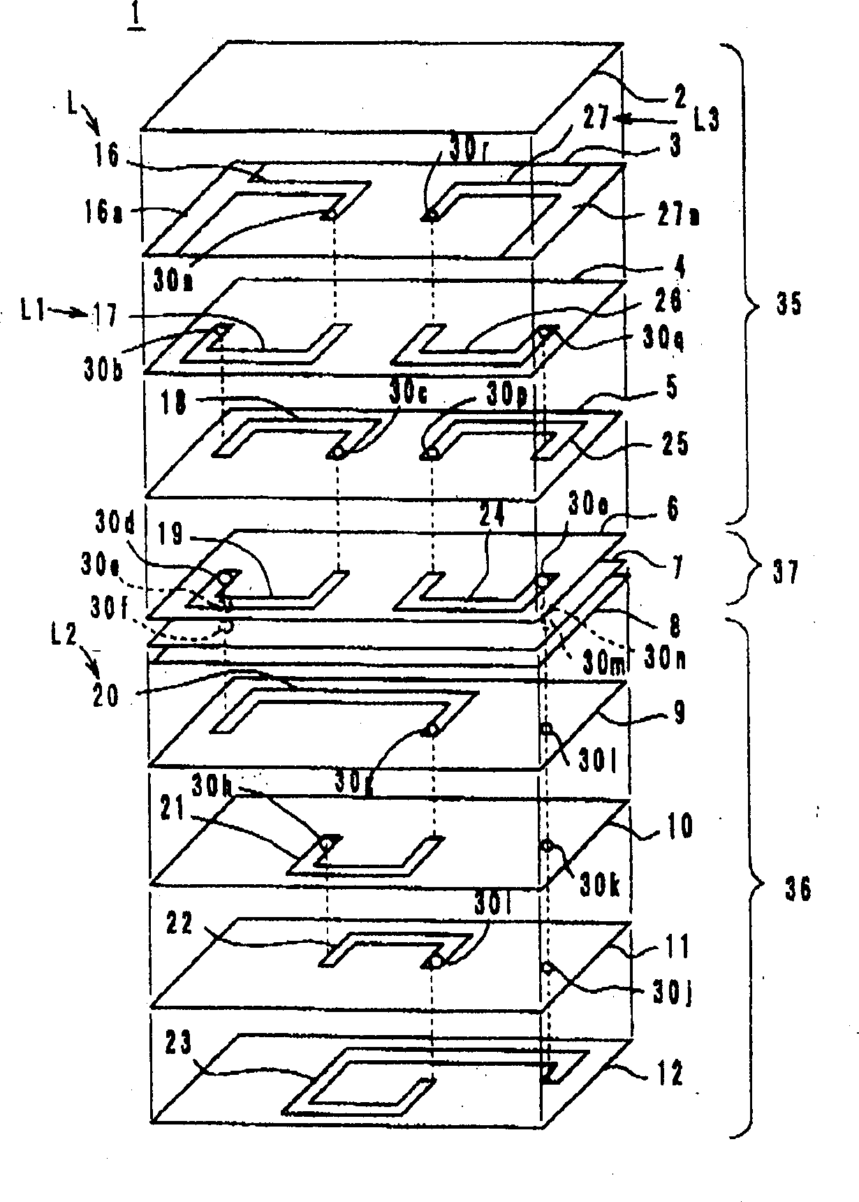
[0019] Embodiments of the multilayer impedance element according to the present invention will be described in detail below with reference to the accompanying drawings. The first embodiment ( Figure 1-Figure 5 )
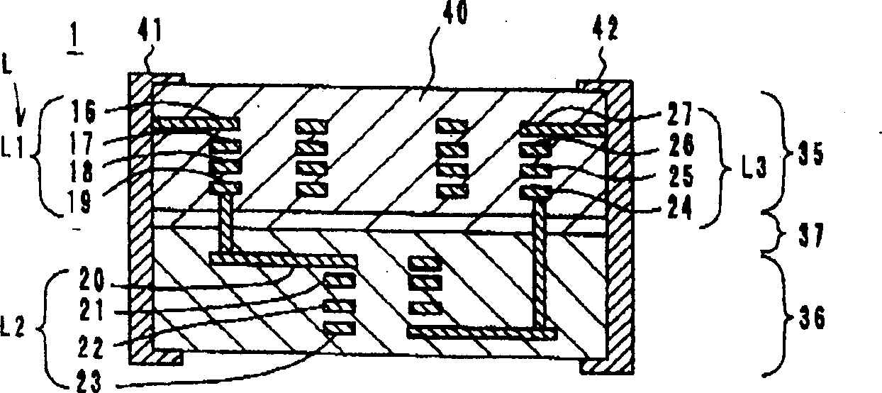
[0020] refer to figure 1 , the multilayer impedance element 1 includes high-permeability magnetic sheets 2 to 6 on which coil wire patterns 16-19 and 24-27 are formed; low-permeability magnetic sheets 8 to 12 which have coils formed thereon Lead pattern 20-23, and middle sheet 7 etc. Magnetic pieces 2-6 are made of insulating paste containing high permeability ferrite powder such as Ni-Cu-Zn ferrite or Mn-Zn ferrite. Similarly, magnetic sheets 8-12 are formed from insulating paste containing low permeability ferrite powder. In the first embodiment of the present invention, the relative permeability μ of the high-permeability magnetic sheet 2-6 is set at 300 or higher, and the relative permeability μ of the low-permeability magnetic sheet 2-6 Set at 100 or lower...
no. 2 example
[0033] Such as Figure 6 As shown in , the multilayer impedance element 51 of the second embodiment of the present invention is formed by superimposing the upper high permeability coils 71 and 72 and the lower low permeability coil 73 . Between the high-permeability coils 71 and 72 and the low-permeability coil 73, intermediate layers 74 and 75 made of, for example, glass or glass ceramics are provided.
[0034] The high-permeability coil 71 is formed by laminating high-permeability magnetic sheets on which the coil wire patterns 52 to 55 are formed. The coil wire patterns 52 to 55 are connected in series through through holes (not shown) formed in the magnetic sheet, thereby forming the first winding portion L1 of the high magnetic permeability coil 71 .
[0035] The high-permeability coil 72 is formed by laminating high-permeability magnetic sheets on which the coil wire patterns 60 to 63 are formed. The coil wire patterns 60 to 63 are connected in series through through h...
no. 3 example
[0039] Third embodiment: Figure 7
[0040] Such as Figure 7 As shown in , the multilayer impedance element 81 of the third embodiment of the present invention is formed by providing high magnetic permeability 101 and 102 on each side of a low magnetic permeability coil 103 . Between the high-permeability coils 101 and 102 and the low-permeability coil 103, intermediate layers 104 and 105 made of, for example, glass or glass ceramics are provided.
[0041] The high-permeability coil 101 is formed by stacking high-permeability magnetic sheets on which coil wire patterns 82 to 85 are formed. The coil wire patterns 82 to 85 are connected in series through through holes (not shown) formed in the magnetic sheet, thereby forming the first winding portion L1 of the high magnetic permeability coil 101 .
[0042] The high-permeability coil 102 is formed by stacking high-permeability magnetic sheets on which the coil wire patterns 90 to 93 are formed. The coil wire patterns 90 to 9...
PUM
 Abstract
Description
Claims
Application Information
 - R&D
- Intellectual Property
- Life Sciences
- Materials
- Tech Scout
- Unparalleled Data Quality
- Higher Quality Content
- 60% Fewer Hallucinations
Browse by: Latest US Patents, China's latest patents, Technical Efficacy Thesaurus, Application Domain, Technology Topic, Popular Technical Reports.
© 2025 PatSnap. All rights reserved.Legal|Privacy policy|Modern Slavery Act Transparency Statement|Sitemap|About US| Contact US: help@patsnap.com