Coating system and process and apparatus for depositing a coating system

a coating system and coating technology, applied in the field of coatings, can solve the problems of increasing the propensity for gum and coke formation, unsatisfactory carbonaceous deposits, and limiting the usefulness of fuel, so as to reduce the adhesion of such deposits

Active Publication Date: 2006-03-16
GENERAL ELECTRIC CO
View PDF11 Cites 11 Cited by
  • Summary
  • Abstract
  • Description
  • Claims
  • Application Information

AI Technical Summary

Benefits of technology

[0009] The present invention provides a coating system for reducing the tendency for hydrocarbon fluids, such as fuels and oils, to form carbonaceous deposits that adhere to fluid containment surfaces. The invention is particularly concerned with carbonaceous gum and coke deposits that form at temperatures from about 600° F. (about 315° C.) to about 800° F. (about 425° C.). According to the invention, a coating system that combines an outermost layer of platinum with an inner ceramic barrier layer formed of silica and / or tantala has been shown to significantly reduce the formation of both gum and coke deposits within the above-noted 315° C. to 425° C. temperature range, as well as reduce the adhesion of such deposits. The coating system is deposited on a wall surface of the component contacted by the hydrocarbon fluid, such that the hydrocarbon fluid contacts and flows across the platinum outermost layer. The outermost layer serves to catalyze the hydrocarbon fluid to form particles of carbonaceous gum substances that are suspended within the hydrocarbon fluid. For this purpose, the outermost layer need only be a monolayer of platinum (several Angstroms in thickness) with a preferred thickness of about 30 to about 100 nm, though thicknesses of up to about 1000 nm are foreseeable. The ceramic barrier layer serves to seal the wall surface from the hydrocarbon fluid to eliminate attachments points for deposits, and also serves to inhibit interdiffusion between the outermost layer and the wall. For these reasons, the ceramic barrier layer has a thickness of at least 50 nm, more preferably at least 100 nm, with a preferred range of about 300 to about 1000 nm, though thicknesses of up to about 5000 nm are foreseeable.

Problems solved by technology

Thermal instability, or in the case of fuels, fuel instability, generally refers to the formation of undesired carbonaceous deposits that occurs when hydrocarbon fluids, such as fuels and lubricating oils, are at elevated temperatures.
Coke formation is the result of high levels of hydrocarbon pyrolysis, and eventually limits the usefulness of the fuel.
However, the propensity for gum and coke formation is increased with certain hydrocarbon fluids for fuels, oils, lubricants, petrochemical processes (plastics and synthetics) and the like, especially those derived from nonpetroleum sources, such as shale and coal, which can exhibit significantly more problems with thermal instability because of their high content of olefins, sulfur and other compounds.
With the advent of higher engine operation temperatures and the use of fuel as a heat sink, there is an increased likelihood that carbonaceous deposits can severely choke the flow of fuel and air through fuel nozzles and swirlers, affecting operating conditions (e.g., mixing of fuel and air, proper flow of fuel and oxygen into the combustor) and may reduce fuel efficiency and increase emissions.
Higher engine operation temperatures also increase the likelihood that carbonaceous deposits will choke the flow of lubrication oil through scavenge lines, leading to loss of lubrication to critical bearings and flooding of the oil sump.
Furthermore, gold readily diffuses into other materials at elevated temperatures, and therefore is unsuitable as a protective coating for high temperature applications, e.g., temperatures associated with gum and coke formation.
Notably, the CBC systems taught by U.S. Pat. Nos. 5,805,973, 5,891,584, 5,923,944, and 6,156,439 do not have the correct optical properties, including low emissivity, to function as radiation shields.
While CBC systems of the prior art can be combined with low-emissivity coatings, a significant drawback is the additional volume, weight and cost incurred.

Method used


Image

  • Coating system and process and apparatus for depositing a coating system
  • Coating system and process and apparatus for depositing a coating system
  • Coating system and process and apparatus for depositing a coating system

Examples


Embodiment Construction

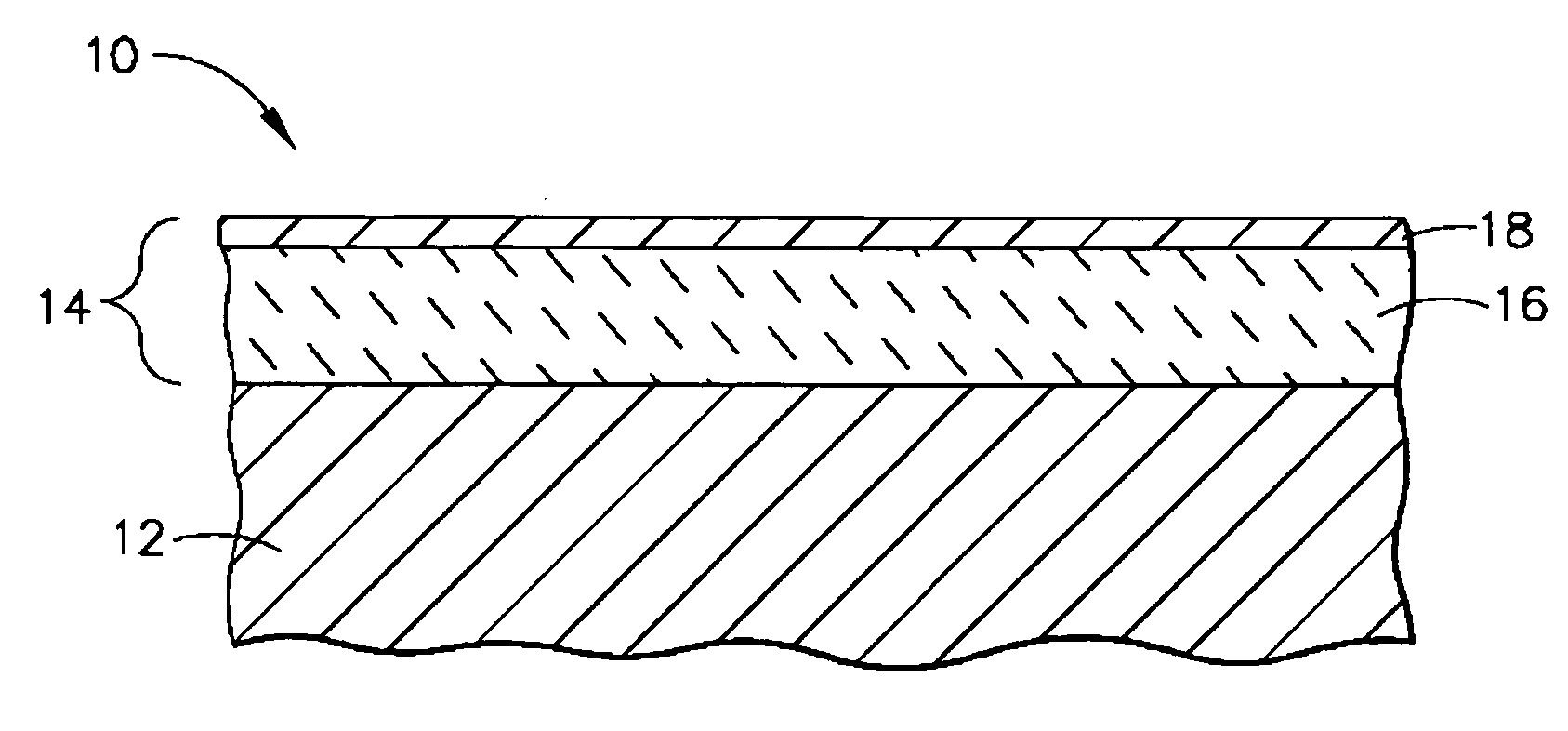
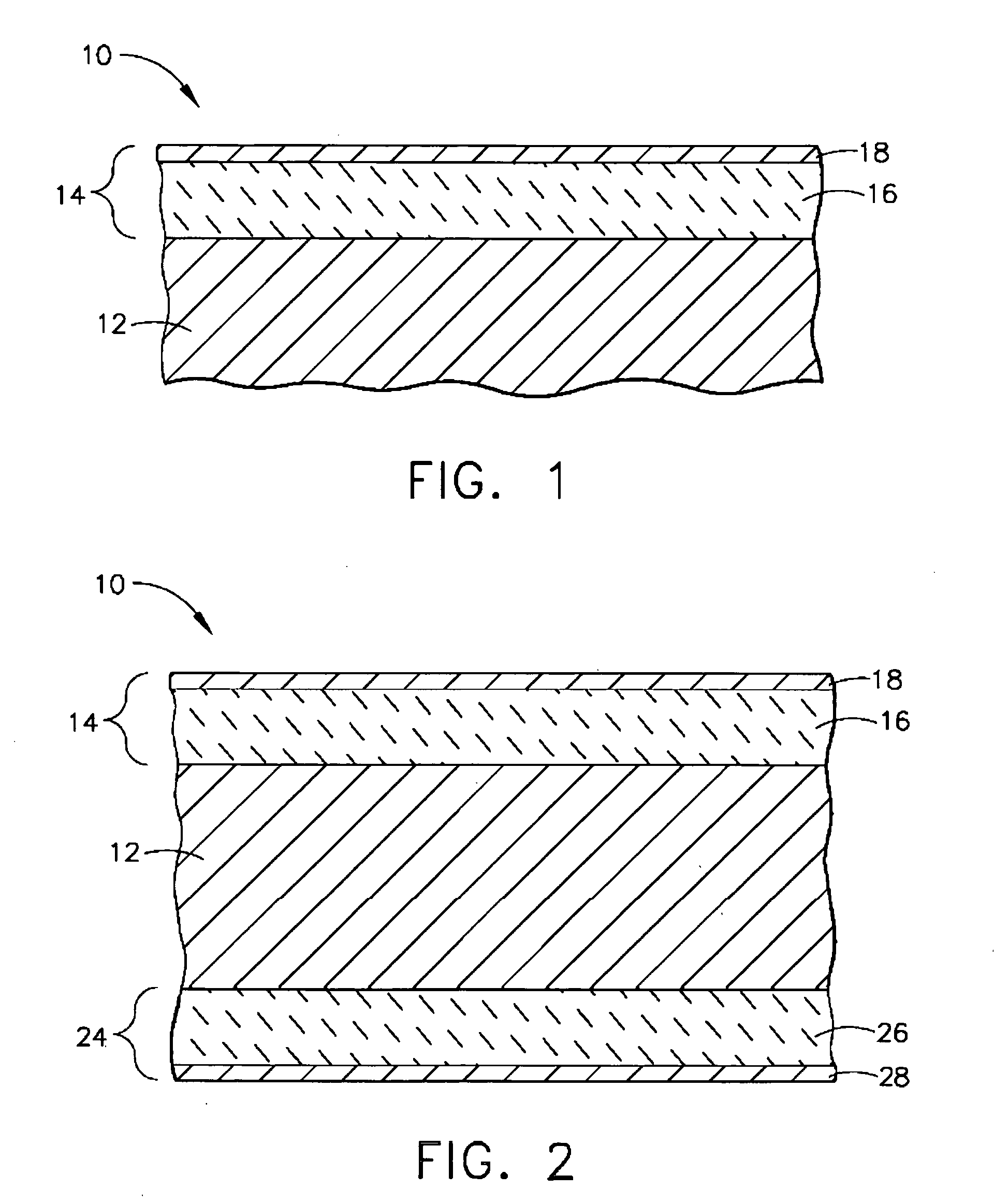
[0018]FIG. 1 represents a coating system 14 for a component 10 having a containment wall 12 that contacts a hydrocarbon fluid (e.g., fuels and oils) at elevated temperatures. The coating system 14 serves to prevent or at least significantly reduce the formation and adhesion of carbonaceous gum and coke deposits that would otherwise form and adhere to the wall 12 at temperatures in the range of about 600 to 800° F. (about 315 to 425° C.). The invention is applicable to any hydrocarbon fluid in which carbonaceous gum (or other polymers) deposits form when the fluid is subjected to elevated temperatures, such as about 105° C. to 345° C., and in which carbonaceous coke deposits form when the fluid is subjected to temperatures generally above 345° C. Such fluids may be pure hydrocarbon or mixtures thereof. Fluid containment articles that can benefit from the present invention may be any component which is adapted to contain or transport hot hydrocarbon fluid, and include but are not limi...


PUM

PropertyMeasurementUnit
thicknessaaaaaaaaaa
temperatureaaaaaaaaaa
thicknessaaaaaaaaaa

Abstract

A coating system for reducing the tendency for hydrocarbon fluids, such as fuels and oils, to form carbonaceous deposits that adhere to fluid containment surfaces. The coating system combines an outermost layer of platinum with an inner ceramic barrier layer of silica and/or tantala. The platinum layer catalyzes the hydrocarbon fluid to form particles of carbonaceous gum substances, and the ceramic barrier layer seals the containment surface from the hydrocarbon fluid to eliminate attachments points for deposits and inhibit interdiffusion between the platinum layer and the containment surface. The invention also encompasses a coating apparatus and process for depositing the coating system.

Description

CROSS REFERENCE TO RELATED APPLICATIONS [0001] This is a continuation-in-part patent application of co-pending U.S. patent application Ser. No. 10 / 711,403, filed Sep. 16, 2004, which is a continuation-in-part patent application of U.S. Pat. No. 6,808,816.BACKGROUND OF THE INVENTION [0002] The present invention relates to coatings that inhibit the formation and adhesion of deposits on surfaces that contact hydrocarbon fluids, such as hydrocarbon fluid containment systems including but not limited to gas turbine engines, furnaces used to produce polymers, diesel engines, etc. More particularly, this invention relates to a coating system for preventing or reducing the deposition of carbonaceous deposits on the surfaces of fuel nozzles, swirlers, oil scavenge lines, and other fuel and lubrication system components of gas turbine engines, as well as a process and apparatus for depositing the coating system. [0003] Thermal instability, or in the case of fuels, fuel instability, generally ...

Claims


Application Information

Patent Timeline
Patent Type & Authority Applications(United States)
IPC IPC(8): B32B9/04F03B3/12
CPCC23C16/06C23C16/44C23C16/448F05B2230/90Y10T428/12611F05B2260/95C23C28/322C23C28/345C23C28/3455F05B2260/63
Inventor DYE, DAVID FORESTACKERMAN, JOHN FREDERICKGUPTA, BHUPENDRA KUMARPINSON, JENNIFER ANNPOTHIER, BRIAN THOMASREYNOLDS, ANTHONY WAYNE
Owner GENERAL ELECTRIC CO
Why Eureka
Try Eureka