Self-regulating brake apparatus for weft-feeding device

A brake device and weft feeder technology, applied in transportation and packaging, textiles, textiles and papermaking, etc., can solve the problems of complex structure of the brake body, increase the size and quality of the brake body, and reduce mass and inertia Effect

Inactive Publication Date: 2002-10-23
L G L ELECTRONICS
View PDF5 Cites 4 Cited by
  • Summary
  • Abstract
  • Description
  • Claims
  • Application Information

AI Technical Summary

Problems solved by technology

[0013] The main drawback of these embodiments is that the construction of the braking body is complicated and, at the most fundamental level, increases the size and mass of the braking body, the inertia of which reaches values ​​that are also unacceptable for a correct and effective self-regulating operation of the braking system

Method used


Image

  • Self-regulating brake apparatus for weft-feeding device
  • Self-regulating brake apparatus for weft-feeding device
  • Self-regulating brake apparatus for weft-feeding device

Examples


Embodiment Construction

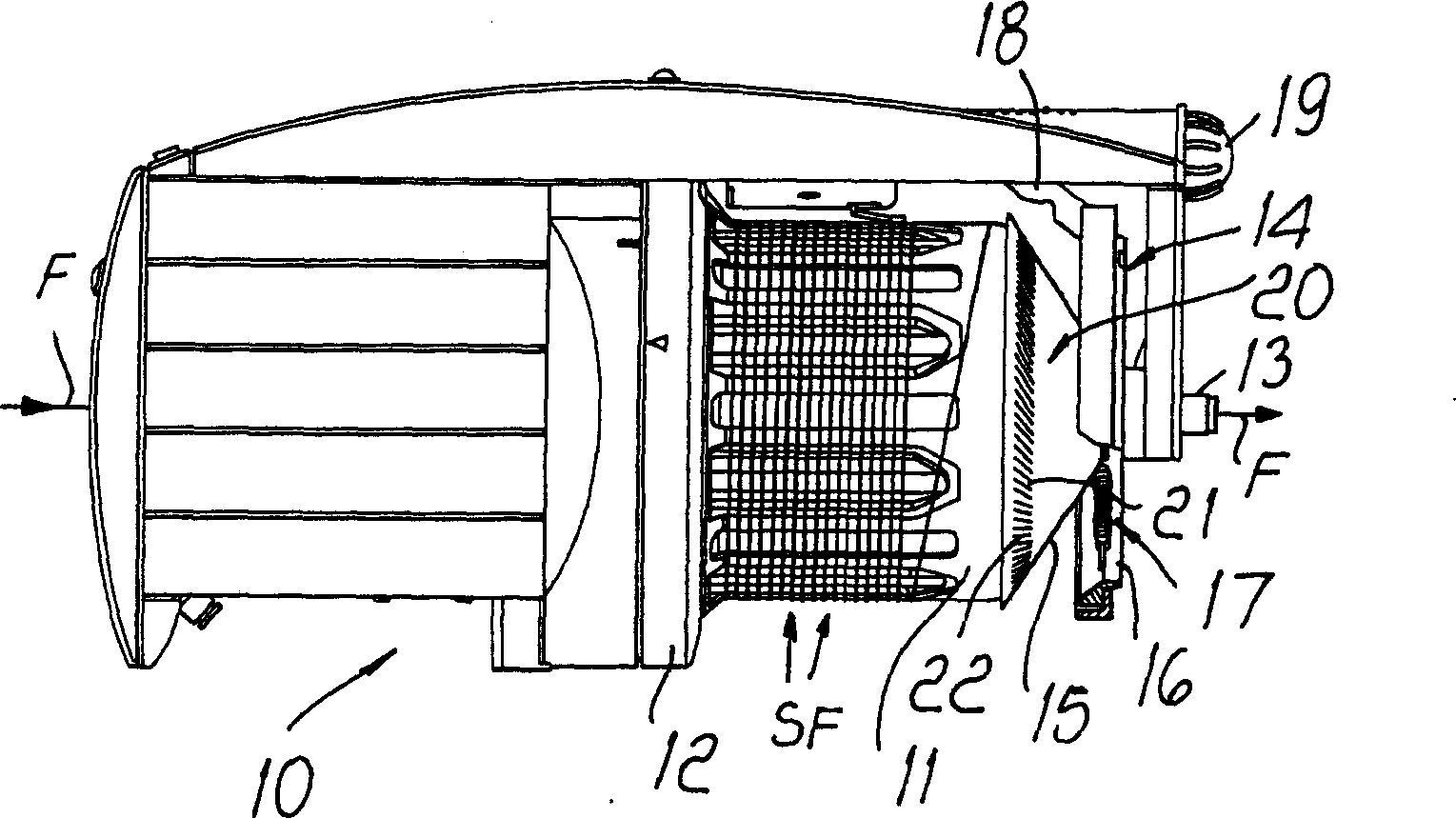
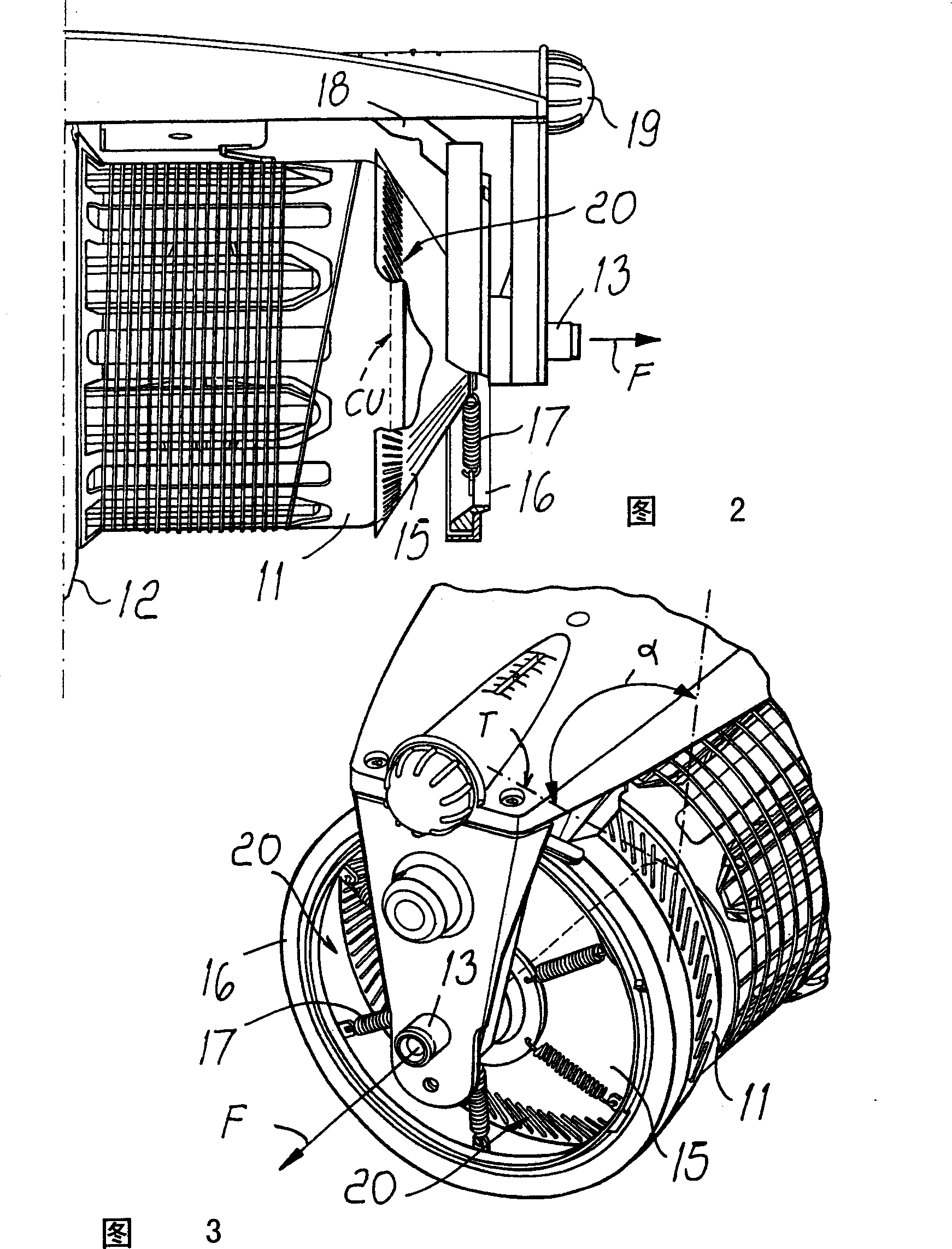
[0030] see first Figures 1 to 6 , reference numeral 10 represents a traditional weft feeder, which includes a fixed drum 11, and a hollow arm rigidly connected with a rotating disc 12 mounted on the base of the drum is wound on the fixed drum 11 in the form of a fishing reel for storage Weft yarns in the form of multi-turn yarns SF. In a manner known per se, when the weaving machine (not shown) requires the yarn F during weft insertion, the yarn F is released from the drum and passed through a thread guide element 13 coaxial with the drum; During the unwinding movement, the yarn is subjected to the action of the self-adjusting device 14 . The device is designed to maintain tension in the yarn by self-adjusting braking action to create a constant or substantially constant tension in the yarn as the yarn advance speed changes during insertion.

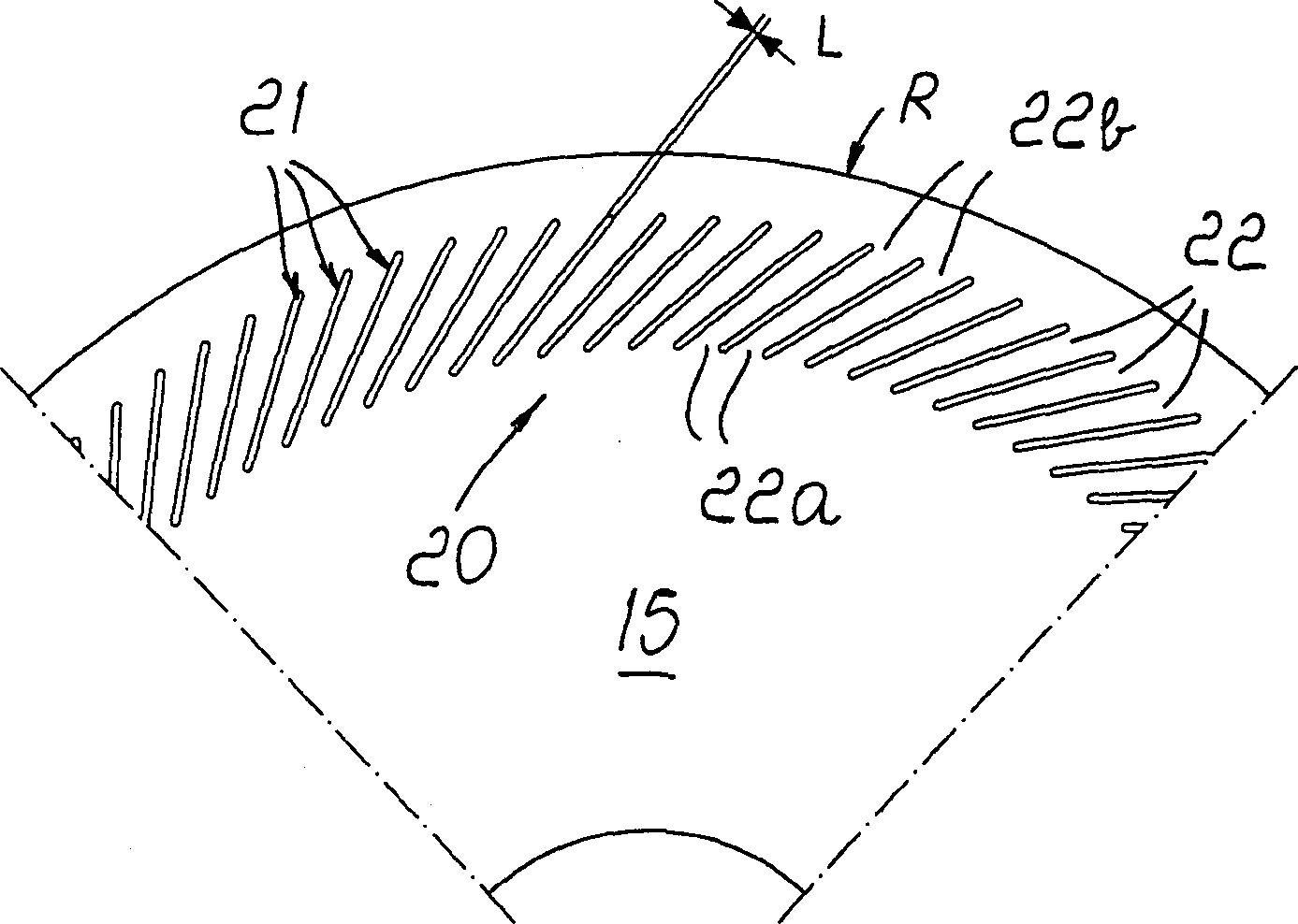
[0031] To this end, the device 14 located between the drum 11 and the yarn guide element 13 comprises a frusto-conical brake body 15...


PUM


Abstract

A self-adjusting braking device for a weft feeder having a frusto-conical braking body (15) acting on said yarn and elastically suspended on the drum of the weft feeder ( 11) and is pushed into elastic tangential contact with the drum along the outer circumference (CU) of the drum's outlet end. The brake body (15) has a discontinuous annular contact element (20) at its larger diameter region (R) in contact with the drum (11), the annular contact element comprising a plurality of through slots (21), the through slots The grooves are arranged equidistant from each other and form a row of contact lamellas (22).

Description

technical field [0001] The present invention relates generally to self-adjusting brakes for use with apparatus for feeding weft yarn to textile machines, particularly gripper or plug-type textile machines. [0002] In particular, the present invention relates to self-adjusting braking devices of the type described in European patent EP-0536088 and Italian patent 1,259,567, which will be briefly referred to below as conventional devices. Background technique [0003] A weft feeder is a device used in the weaving process, usually consisting of a fixed cylindrical drum on which an arm rotating in the manner of a fishing reel winds multiple coils of yarn, which constitute the weft storage; the means of advancing towards the end of the drum; and the braking means at the outlet end, for braking the yarn, as required in looms and the like, for releasing the yarn from the drum at each weft insertion, by This provides the correct mechanical tension, which is essential for correct un...

Claims


Application Information

Patent Timeline
Patent Type & Authority Applications(China)
IPC IPC(8): B65H51/22D03D47/36
CPCD03D47/364
Inventor P·泽诺尼R·卡斯泰利G·佩德里尼
Owner L G L ELECTRONICS
Why Eureka
Try Eureka