Mechanism for milling impeller inducer of centrifugal compressor with ordinary milling machine

The technology of centrifugal compressor and air guide impeller is applied in the field of processing devices, which can solve the problems of unstable quality, low impeller strength and high processing cost, and achieve the effects of simple structure, convenient operation and use, and stable product quality.

Inactive Publication Date: 2002-11-13
周国强
View PDF0 Cites 6 Cited by
  • Summary
  • Abstract
  • Description
  • Claims
  • Application Information

AI Technical Summary

Problems solved by technology

At present, there are two methods of manufacturing semi-open impellers: CNC milling and welding. The former CNC milling is milled by computer programming on a five-axis CNC milling machine. This processing method has high precision and reliable quality of the blade profile. The impeller has high strength, but the five-axis CNC milling machine is extremely expensive and the processing cost is high; the latter is manufactured by welding, which first molds the blades into shape, and then welds the blades to the wheel one by one. The disadvantage of this manufacturing method is The manufacturing accuracy of the blade profile is low, affected by many factors such as molding, welding process, heat treatment, etc., the quality is unstable, and the impeller strength is low

Method used


Image

  • Mechanism for milling impeller inducer of centrifugal compressor with ordinary milling machine
  • Mechanism for milling impeller inducer of centrifugal compressor with ordinary milling machine
  • Mechanism for milling impeller inducer of centrifugal compressor with ordinary milling machine

Examples


Embodiment Construction

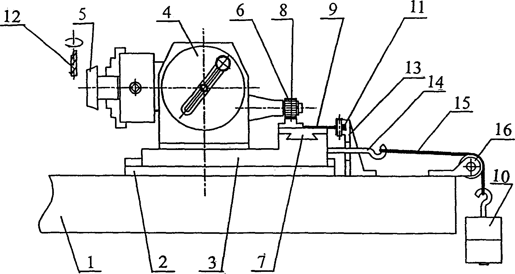
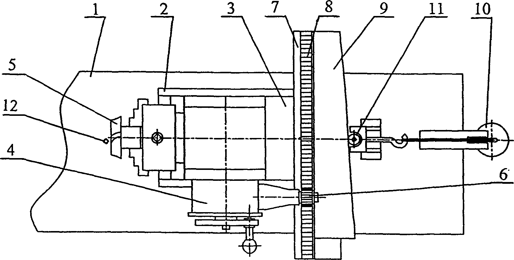
[0012] Such as figure 1 , figure 2 As shown, it includes a longitudinal sliding seat 2 installed on the vertical milling machine table 1, and a milling machine dividing head 4 is installed on the sliding plate 3 that can move longitudinally on the longitudinal sliding seat 2. The sliding plate 3 is equipped with a horizontal sliding plate 7 and a hook. The screw 14, the transmission gear 6 on the indexing head 4 meshes with the rack 8 fixed on the horizontal slide 7, the template 9 is fixed on the horizontal slide 7, the vertical milling machine table 1 is equipped with a roller frame 13 and a pulley frame 16, Nylon rope 15 on the hook screw 14 hangs heavy hammer 10 through the pulley on the pulley frame 16, and the roller 11 on the roller frame 13 is pushed against template 9 sides all the time.

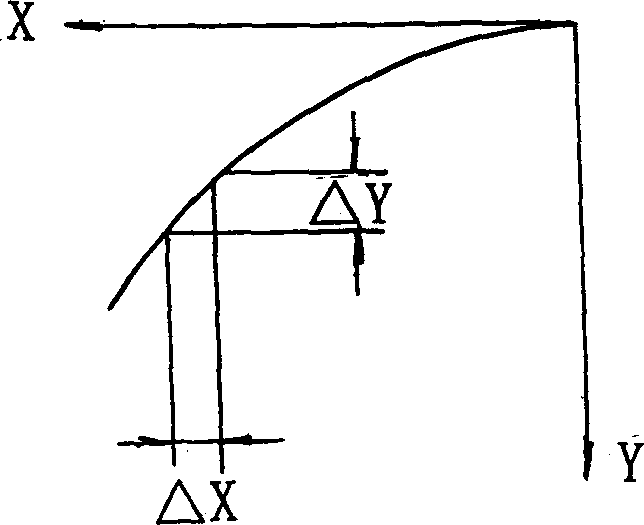
[0013] Such as image 3 , Figure 4 As shown, according to the profile line coordinates on the average diameter of the vane inlet of the vane, the template curve and the vane cu...


PUM


Abstract

A mechanism for milling the impeller inducer is centrifugal compressor on the ordinary milling machine has a longitudinal slide seat installed to the bench of vertical milling machine, an index head installed to the slide plate moving on the said longitudinal slide seat and the transverse slide plate and gib-headed screw installed on the said slide plate. A copying plate is installed to the said transverse slide plate. A weight is hung from the gib-headed screw via nylon string and pulley, forcing the roller always in contact with the side surface of copying plate. Its advantages are simple structure and high and stable quality of products.

Description

technical field [0001] The invention relates to a device for machining guide wheels of centrifugal compressors. Background technique [0002] Centrifugal compressor radial straight blade semi-open impeller has the advantages of high single-stage pressure ratio and good strength, and is widely used in medium and small compressors. At present, there are two methods of manufacturing semi-open impellers: CNC milling and welding. The former CNC milling is milled by computer programming on a five-axis CNC milling machine. This processing method has high precision and reliable quality of the blade profile. The impeller has high strength, but the five-axis CNC milling machine is extremely expensive and the processing cost is high; the latter is manufactured by welding, which first molds the blades into shape, and then welds the blades to the wheel one by one. The disadvantage of this manufacturing method is The manufacturing precision of the blade profile ...

Claims


Application Information

Patent Timeline
Patent Type & Authority Applications(China)
IPC IPC(8): B23C3/18
Inventor 吴若琨周国强
Owner 周国强
Why Eureka
Try Eureka